Routing extensions for telecommunication network system and method
Inactive Publication Date: 2006-01-24
AMERICAN TELEPHONE & TELEGRAPH CO
View PDF5 Cites 19 Cited by
Summary
Abstract
Description
Claims
Application Information
AI Technical Summary
This helps you quickly interpret patents by identifying the three key elements:
Problems solved by technology
Method used
Benefits of technology
[0008]A distributed features system is disclosed which permits a telecommunication network to accommodate the creation of open multimedia services. It is an object of the present invention to create an architecture that facilitates modularity and compositional service creation. It is another object of
Problems solved by technology
The feature-interaction problem arises from the incremental, feature-by-feature, extension of telecommunications system functionality.
As new features such as call forwarding, call waiting, or three-way calling have been added to telecommunication systems, it has become increasingly difficult to manage the behavioral complexity of the features and their interactions.
Redesign of old features to fit smoothly with the new features is scarcely ever a practical option.
Eventually, the resulting complexity damages the quality and productivity of all phases of telecommunication software development.
Modern networks and devic
Method used
Image
Click on the blue label to locate the original text in one second.
Reading with bidirectional positioning of images and text.
Examples
Embodiment Construction
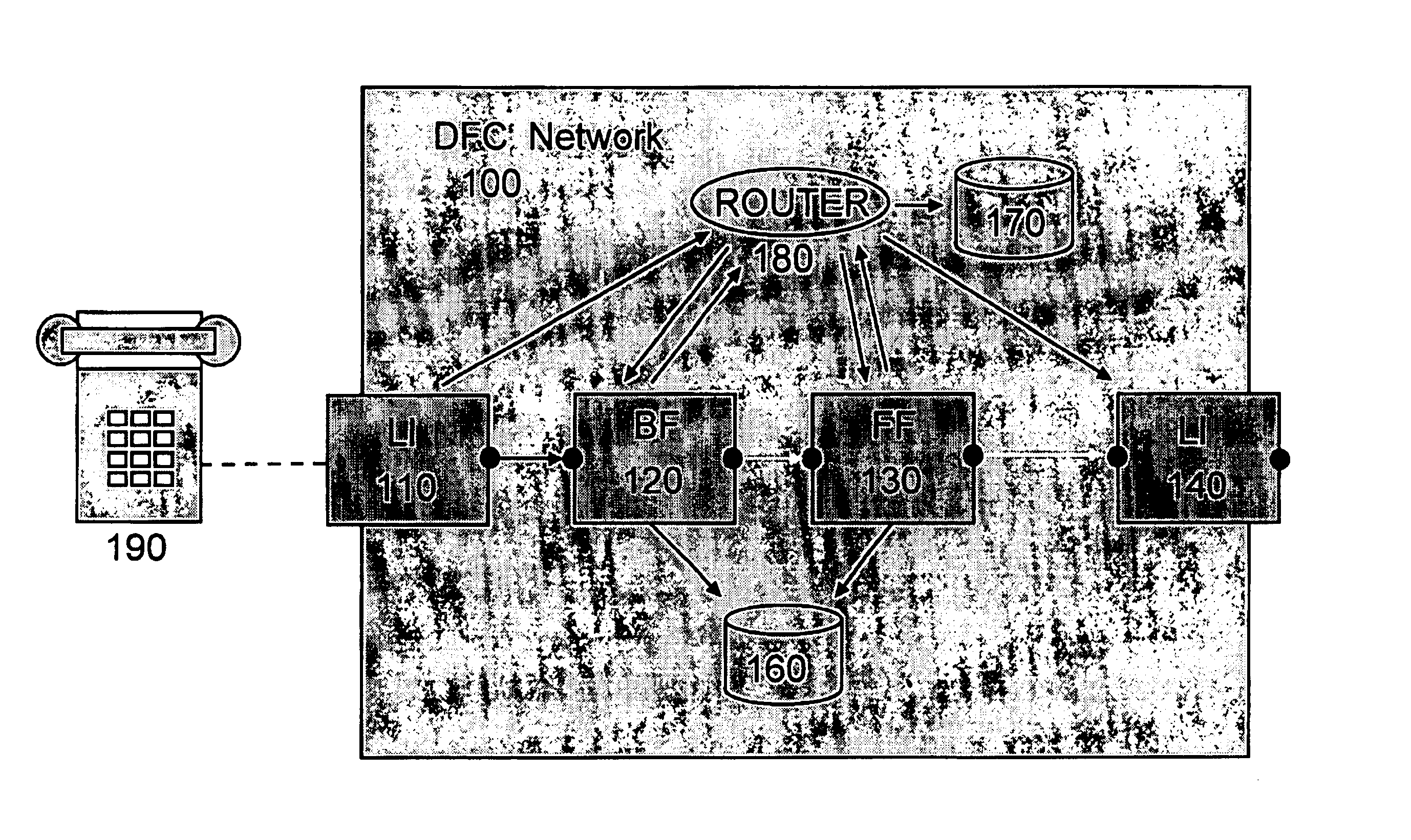
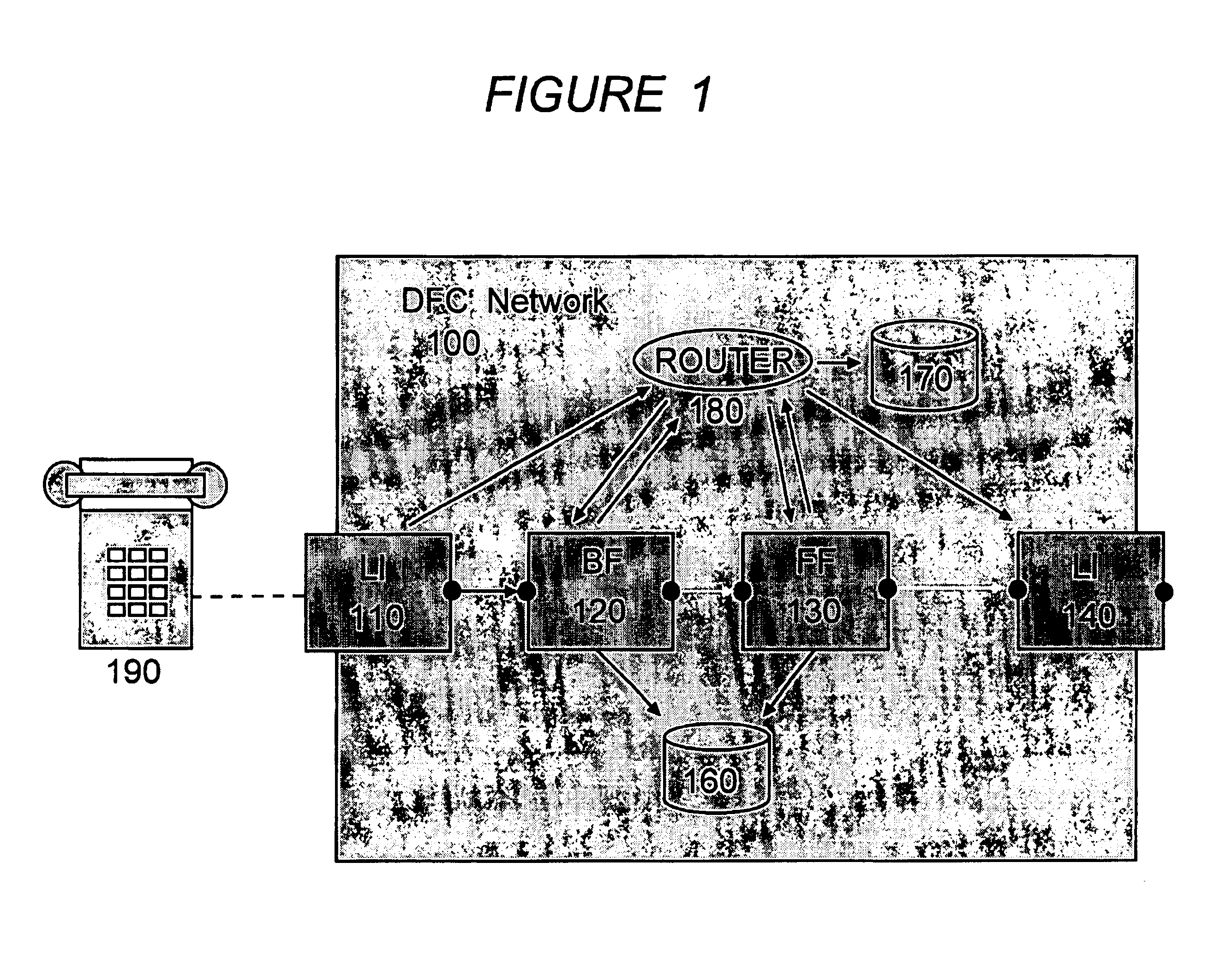
[0020]FIG. 1 sets forth an example of an abstract diagram of a distributed feature system, adapted in accordance with a preferred embodiment of the present invention. The distributed feature system represents a virtual architecture for describing telecommunication services by separating logic that provides service feature functionality into separate distributed components. The present invention is described in the context of DFC, although the principles of the present invention can be readily extended by one of ordinary skill in the art to other distributed feature architectures.
[0021]As depicted in FIG. 1, the virtual network 100 comprises one or more routers 180 and a plurality of primitive components called “boxes”, e.g. 110 through 140 in FIG. 1 (these are referred to interchangeably as boxes or modules). The boxes have well-defined interfaces and have structured access to operational data (e.g. depicted in FIG. 1 as 160) to help them fulfill their designated roles in the teleco...
PUM
Abstract
A distributed features system is disclosed which permits a telecommunication network to accommodate the creation of open multimedia services. It is an object of the present invention to create an architecture that facilitates modularity and compositional service creation. It is another object of the present invention to support multimedia services, e.g. services that include voice, graphics, video and text components. It is another object of the present invention to provide an architecture that is general, flexible, permits third party feature development, and can interact with other networks.
Description
CROSS REFERENCE TO RELATED APPLICATIONS[0001]This application claims priority to Provisional Application “Routing Extensions For Telecommunications Network System and Method,” Ser. No. 60 / 154,877, filed on Sep. 20, 1999; “DFC: Signaling and Media Extensions,” Ser. No. 60 / 166,563, filed on Nov. 19, 1999; “Eclipse: Software Architecture for Next Generation Telecommunications,” Ser. No. 60 / 199,089, filed on Apr. 21, 2000; “New Feature Interactions in Mobile and Multimedia Telecommunication Services,” Ser. No. 60 / 204,334, filed on May 15, 2000, the contents of which are incorporated by reference herein.[0002]This application is related to Utility Application, “Telecommunication Network System and Method,” Ser. No. 09 / 034,681, filed on Mar. 4, 1998, by the same inventors, which is incorporated by reference herein.FIELD OF THE INVENTION[0003]The invention relates to telecommunications networks, and more particularly to advanced architectures for the description of telecommunication servic...
Claims
Application Information
Patent Timeline
Application Date:The date an application was filed.
Publication Date:The date a patent or application was officially published.
First Publication Date:The earliest publication date of a patent with the same application number.
Issue Date:Publication date of the patent grant document.
PCT Entry Date:The Entry date of PCT National Phase.
Estimated Expiry Date:The statutory expiry date of a patent right according to the Patent Law, and it is the longest term of protection that the patent right can achieve without the termination of the patent right due to other reasons(Term extension factor has been taken into account ).
Invalid Date:Actual expiry date is based on effective date or publication date of legal transaction data of invalid patent.