Variable pitch fan

a variable-pitch fan and fan blade technology, which is applied in the direction of wind motors with parallel air flow, wind motors with perpendicular air flow, liquid fuel engine components, etc., can solve the problems of low efficiency and high noise emissions, no one arrangement has been developed and commercialised, and the power supply is great, so as to reduce the absolute speed and increase the efficiency

Inactive Publication Date: 2006-01-31
PIETRICOLA PAOLO
View PDF17 Cites 21 Cited by
  • Summary
  • Abstract
  • Description
  • Claims
  • Application Information

AI Technical Summary

Benefits of technology

[0017]It's also an object of this invention to provide, in one hand, a stator row upstream the rotor (the “nozzle” ones because are suitable to increase the relative speeds) which are twisted in a such particular way that allows in

Problems solved by technology

But, high difference of speed amongst the inlet and the outlet of a fan mean great power to be supplied,

Method used


Image

  • Variable pitch fan
  • Variable pitch fan
  • Variable pitch fan

Examples


Embodiment Construction

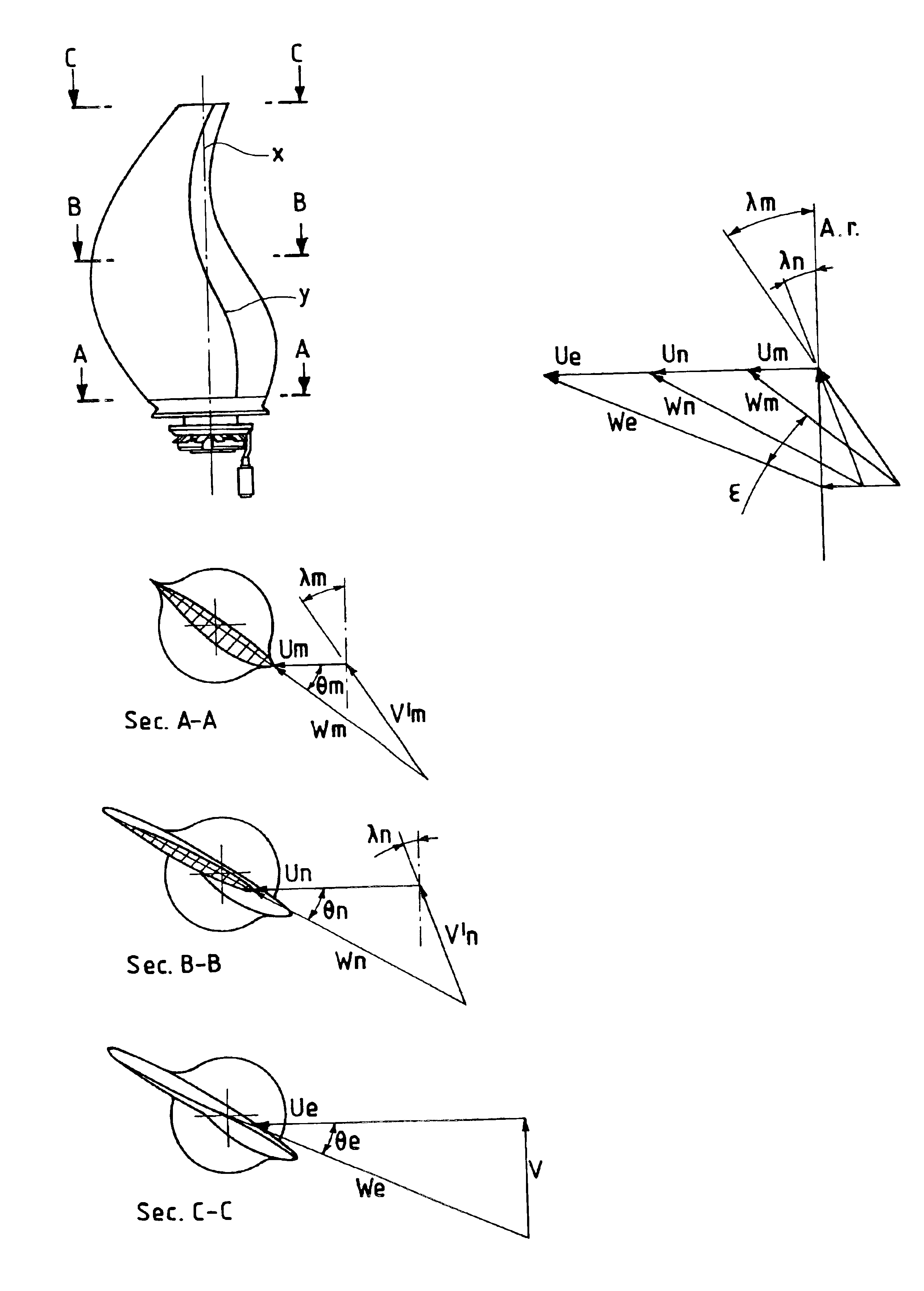
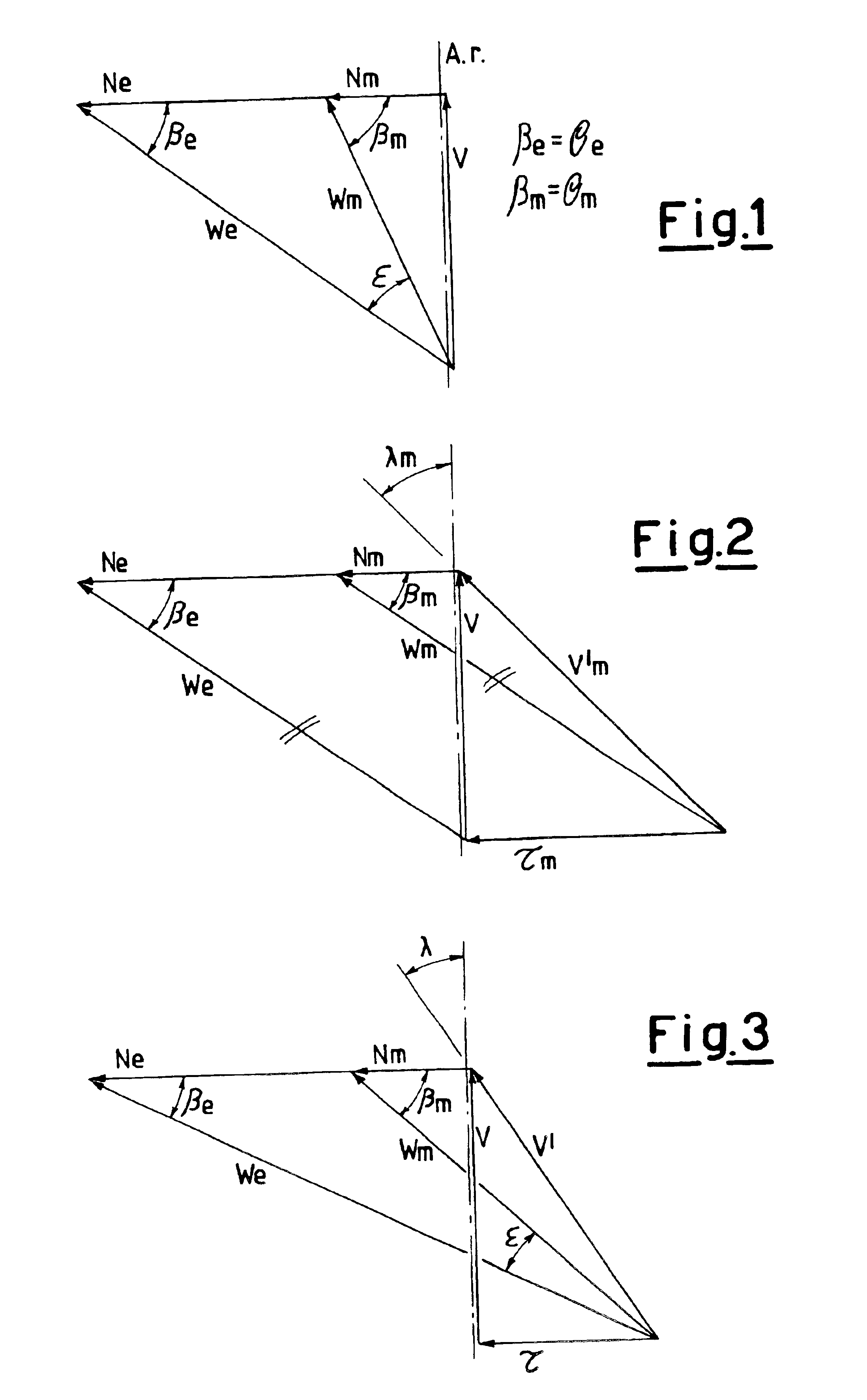
[0033]To explain the introduced features in relation to the known art, this description will begin from the speed triangles known in this section.

[0034]The field diagram is a vectorial diagram in which are represented the speed triangles of all the rotor blade sections. The main purpose of this diagram is to determine geometrically the twist of the propellers. The twist is defined from the stagger angles θ along the rotor blades. θ are the angles subtended from the turning speed U and the relative speed W (also defined with the symbol β) determined in the design phase (refer to FIG. 1). In the field diagrams outlined in the enclosed figures, only the speed triangles to the root m and to the tip e of the blades have been represented. The values of the speeds are brought back in this diagram transforming them from m / sec in cm. The reference necessary to draw this diagram is the propeller spin axe A.R. The speeds U are perpendicular to A.R., proportional to the radius and depend from t...


PUM


Abstract

A variable pitch fan, particularly for propulsion, of the type comprising a rotor and at least two stages of stator blade rows positioned upstream and downstream of the rotor, wherein the rotor blades (8) are of the variable pitch type and have a sinusoidal shape, are of the twisted type (1) or of the constant deflection type (2) and the stator blades (25), positioned downstream of the rotor, are of the twisted type. This rotor blade design allows a reduction of both the torque necessary to activate the variable pitch systems (lither actuator system) and the turning moments due to the centrifugal force. The proposed fan can be set in rotation by a conic couple of gears, contained in a gear oil sump positioned downstream the rotor, by means of one power shaft contained inside the stator blade.
The variable pitch fan further provides a stator row upstream the rotor which are twisted in a manner that allows increased efficiency. The stator row downstream the rotor has a movable twisted part actuated by way of a simple electro mechanic system.
This invention even further provides a light screw female system, actuated by an electric motor, to rotate the variable pitch rotor blades.

Description

FIELD OF THE INVENTION[0001]This invention refers to a turbine engine with variable pitch rotor blades having a drop shape; the engine according to the invention can advantageously also incorporate a “twisted” or a “constant deflection” stator blade row in the Air-Intake and, in the nozzle, a stator blade row with a movable twisted part.[0002]The propulsion system, wherein the movable parts are controlled and actuated electrically, can be employed both for the aeronautic propulsion and for the marine propulsion.BACKGROUND OF THE INVENTION[0003]As it is well known in the state of the art, running a fix pitch fan to high speed, it's necessary to design the twist of the rotor blades with high pitch angles. This implies the ejected air speeds to be high also in the low advancement speed (i.e. lending and take-off phases). But, high difference of speed amongst the inlet and the outlet of a fan mean great power to be supplied, low efficiency and high noise emissions. Hence from the 70's h...

Claims


Application Information

Patent Timeline
IPC IPC(8): F01D1/02B63H7/00B63H11/08F01D7/00F01D17/16F04D29/32F04D29/54
CPCF01D7/00F01D17/162F04D29/542F04D29/324B63H7/00B63H11/08B63H2011/081F05D2250/184F05B2240/3121Y02T50/671Y02T50/673F05D2260/74B63H2011/046F04D29/544Y02T50/60
Inventor PIETRICOLA, PAOLO
Owner PIETRICOLA PAOLO
Why Eureka
Try Eureka