
Multi-level conductive lines with reduced pitch

a technology of multi-level conductive lines and conductive lines, which is applied in the field of integrated circuits, can solve the problems of reducing the minimum resolution or feature size of the line, affecting the efficiency of the integrated circuit, so as to reduce the capacitance of the conductive line, reduce the effective spacing, and reduce the capacitance for a given pitch

Inactive Publication Date: 2006-01-31
POLARIS INNOVATIONS
View PDF14 Cites 219 Cited by
  • Summary
  • Abstract
  • Description
  • Claims
  • Application Information

AI Technical Summary

Benefits of technology

[0006]The invention relates to multi-level conductive lines having reduced capacitance for a given pitch. In one embodiment, at least conductive lines on one of the multi-levels comprise non-rectangu

Problems solved by technology

A limiting factor to reducing the line pitch is the minimum resolution or feature size (F) of a specific lithographic tool.
However, when the line pitch is reduced, the line capacitance increases due to the larger line-to-line capacitance.
Larger line capacitance is undesirable as it increases power consumption.
In addition, the larger line capacitance can negatively affect the signal integrity due to coupling noise from neighboring lines, reducing yield.

Method used


Image

  • Multi-level conductive lines with reduced pitch
  • Multi-level conductive lines with reduced pitch
  • Multi-level conductive lines with reduced pitch

Examples


Embodiment Construction

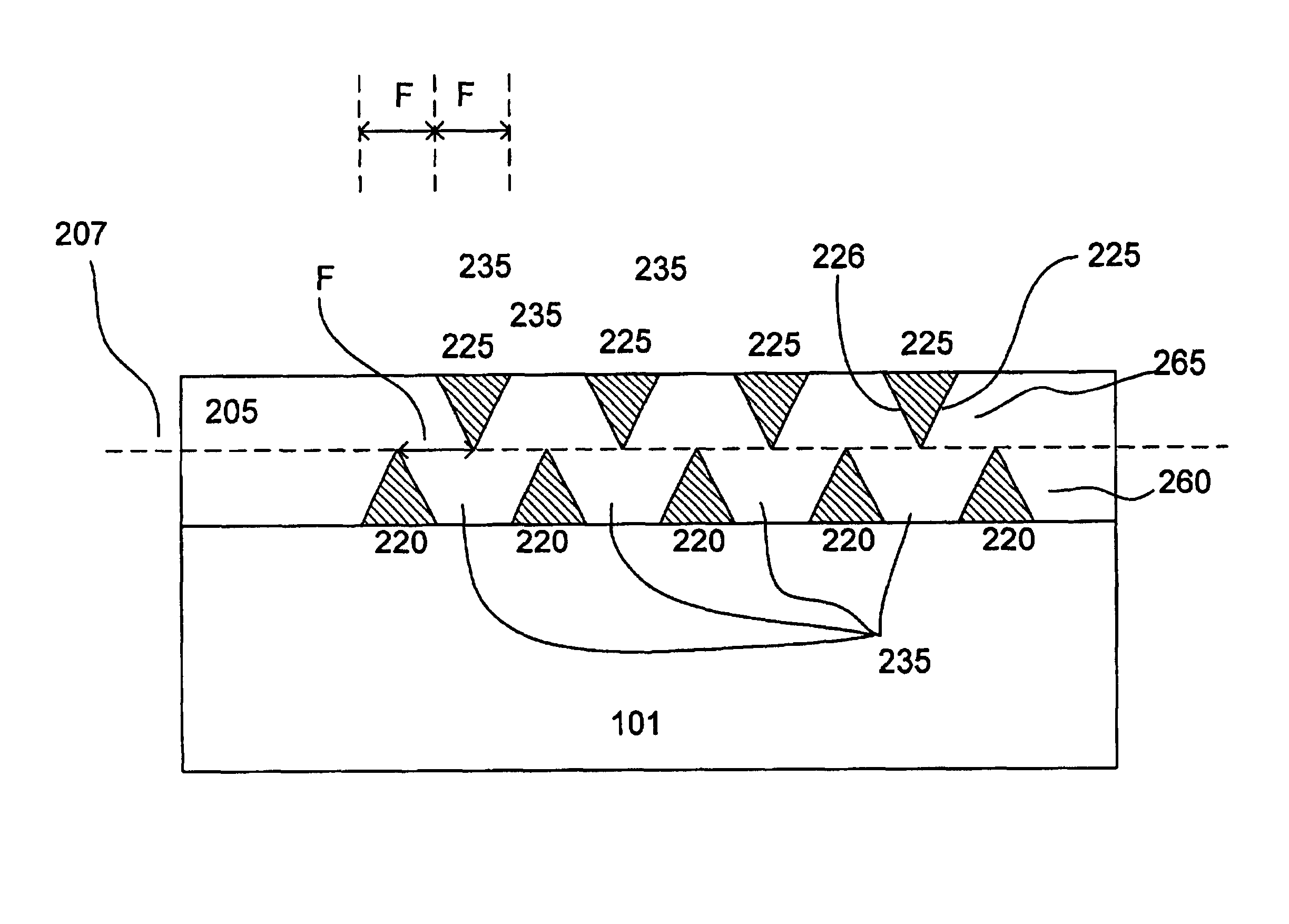
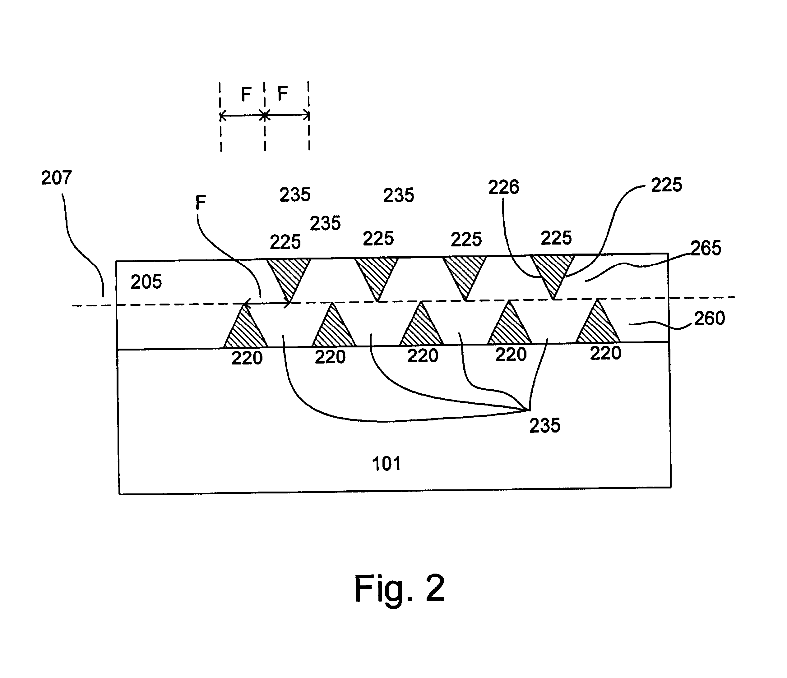
[0012]FIG. 2 shows an integrated circuit having multi-level conductive lines in accordance with one embodiment of the invention. A substrate 101 is provided on which conductive lines 220 and 225 are formed. Typically, the width of a conductive line is limited to about 1F. Line widths of greater than 1F can also be used, as desired. The conductive lines are located on first and second conductive levels 260 and 265 and isolated from each other by a dielectric layer 205. The substrate, for example, comprises a dielectric layer over a semiconductor substrate having circuit features formed thereon. Contacts are provided to electrically couple the circuit features with the conductive lines. However, for sake of simplification, the contacts and circuit features are not shown.

[0013]In accordance with the invention, at least the conductive lines on one of the levels comprise non-rectangular cross-sections. Preferably, conductive lines in the different levels comprise non-rectangular cross-se...


PUM


Abstract

The invention describes the use of conductive lines having a non-rectangular shaped cross section to reduce line capacitance for a given pitch. Such conductive lines can reduce the height of integrated circuits with multi-level conductive lines without increasing line-to-line capacitance.

Description

[0001]This application is a continuation-in-part of U.S. patent application U.S. Ser. No. 09 / 751,492, filed Dec. 28, 2000, now U.S. Pat. No. 6,469,392.FIELD OF THE INVENTION[0002]The present invention relates to integrated circuits and, more particularly, to integrated circuits with multi-level conductive lines with reduced line pitch.BACKGROUND OF THE INVENTION[0003]In integrated circuits, parallel conductive lines are widely used to interconnect circuit elements. FIG. 1 shows conductive lines 120 formed on a substrate 101, separated by line spaces 135. The width of the line spacing and conductive line is referred to as the “line pitch”. A limiting factor to reducing the line pitch is the minimum resolution or feature size (F) of a specific lithographic tool. With the line spacing and line width equal to 1F each, the minimum line pitch is 2F.[0004]One technique for reducing line pitch below 2F is to provide an additional level 165 on which second conductive lines 125 are formed. By...

Claims


Application Information

Patent Timeline
IPC IPC(8): H01L23/528H01L23/522
CPCH01L23/5222H01L23/5283H01L2924/0002H01L2924/00
Inventor PARK, YOUNG-JINMUELLER, GERHARD
Owner POLARIS INNOVATIONS
Features
  • Generate Ideas
  • Intellectual Property
  • Life Sciences
  • Materials
  • Tech Scout
  • Unparalleled Data Quality
  • Higher Quality Content
  • 60% Fewer Hallucinations
Learn More