Calibration of a device location measurement system that utilizes wireless signal strengths

a wireless signal strength and location measurement technology, applied in direction finders using radio waves, navigation instruments, instruments, etc., can solve the problems of requiring tedious and time-consuming manual labor, administrators are reluctant to even keep the location of printers updated, and the accuracy of the level of accuracy is high. , to achieve the effect of reducing nois

Inactive Publication Date: 2006-01-31
MICROSOFT TECH LICENSING LLC
View PDF6 Cites 61 Cited by
  • Summary
  • Abstract
  • Description
  • Claims
  • Application Information

AI Technical Summary

Benefits of technology

[0017]One embodiment provides a more precise location measurement methodology, where calibration is accomplished by placing the receiver at one point at the location to be measured, and measuring signal properties based upon that single receiver location. The user selects the approximate location of the receiver on a map that shows the position of the receiver relative to the location to be measured. Additionally, an averaging function is provided that averages the last ten computed (x,y) locations to further reduce noise.

Problems solved by technology

However, this level of accuracy comes at a price of requiring tedious and time-consuming manual labor in order to obtain spatially high-density calibration data of signal strengths as a function of location.
It is often be impracticable to expect anyone to spend resources on such work—when presented with such prospect as part of a new product, software product planners often balk, complaining that system administrators are reluctant to even keep locations of printers updated, much less create and maintain a high-resolution table of IEEE 802.11 signal strengths.
Some of the conventional systems described hereinabove are explicitly working toward more accuracy, but at the expense of increased calibration effort.

Method used


Image

  • Calibration of a device location measurement system that utilizes wireless signal strengths
  • Calibration of a device location measurement system that utilizes wireless signal strengths
  • Calibration of a device location measurement system that utilizes wireless signal strengths

Examples


application examples

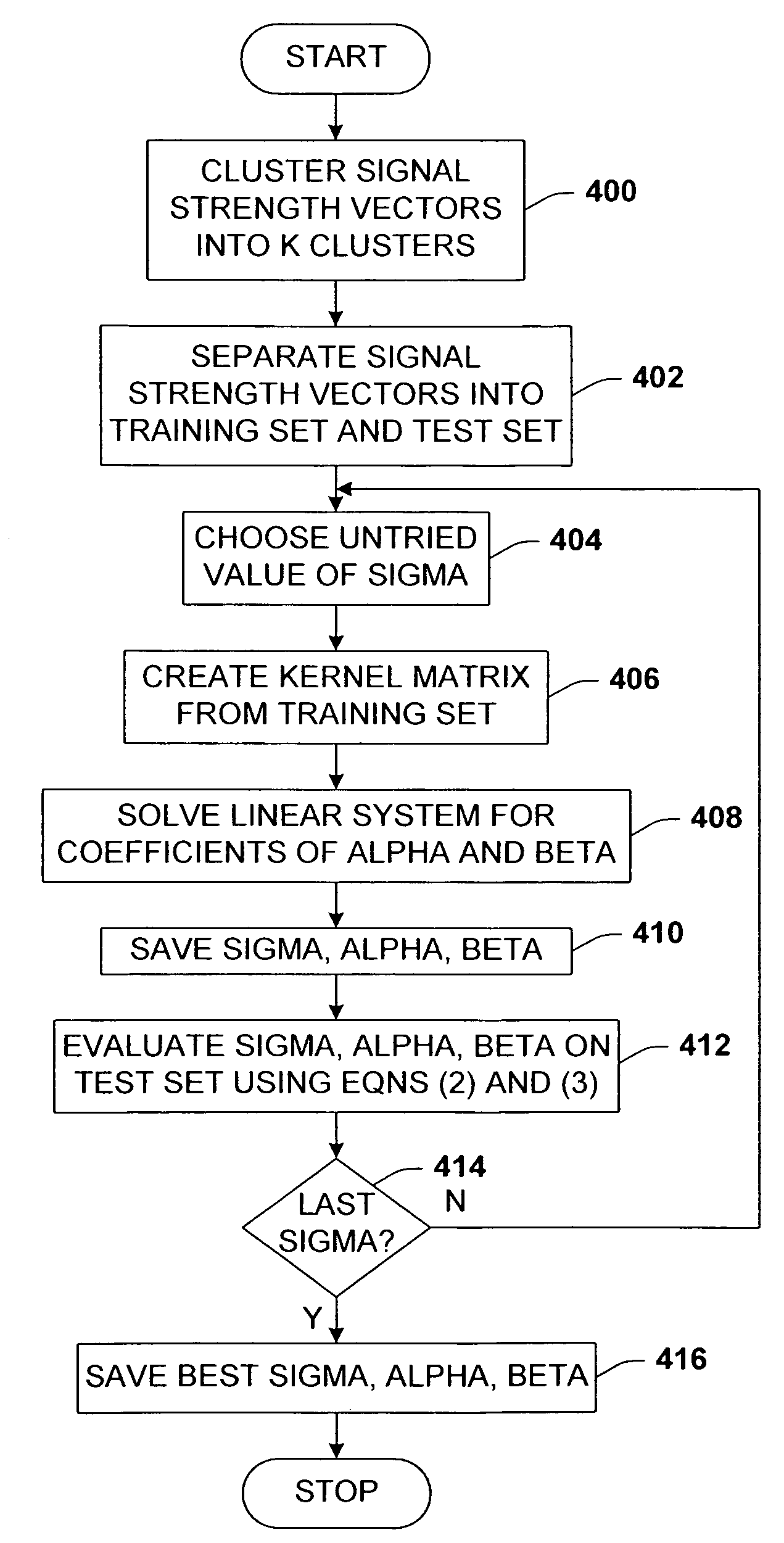
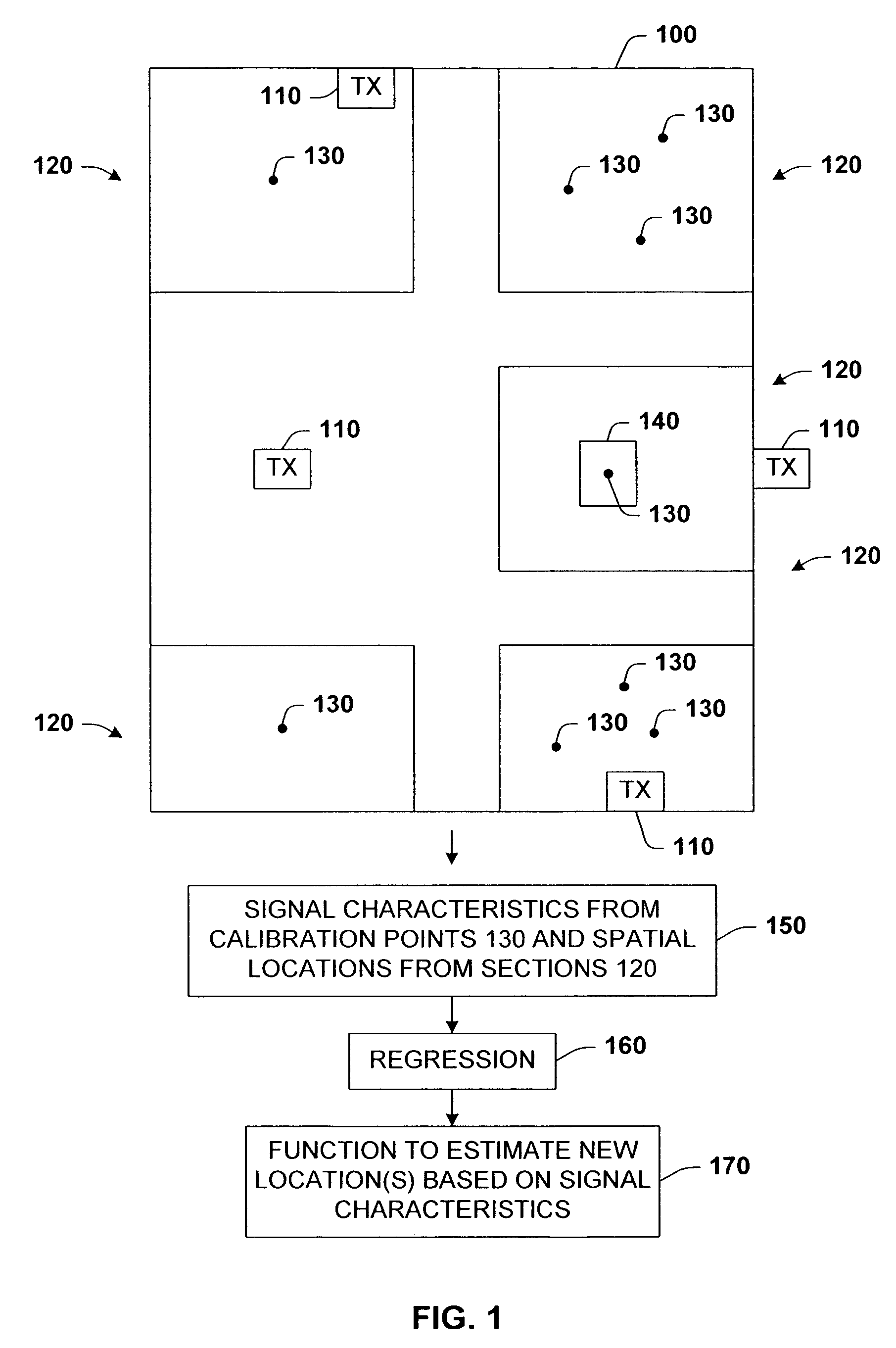
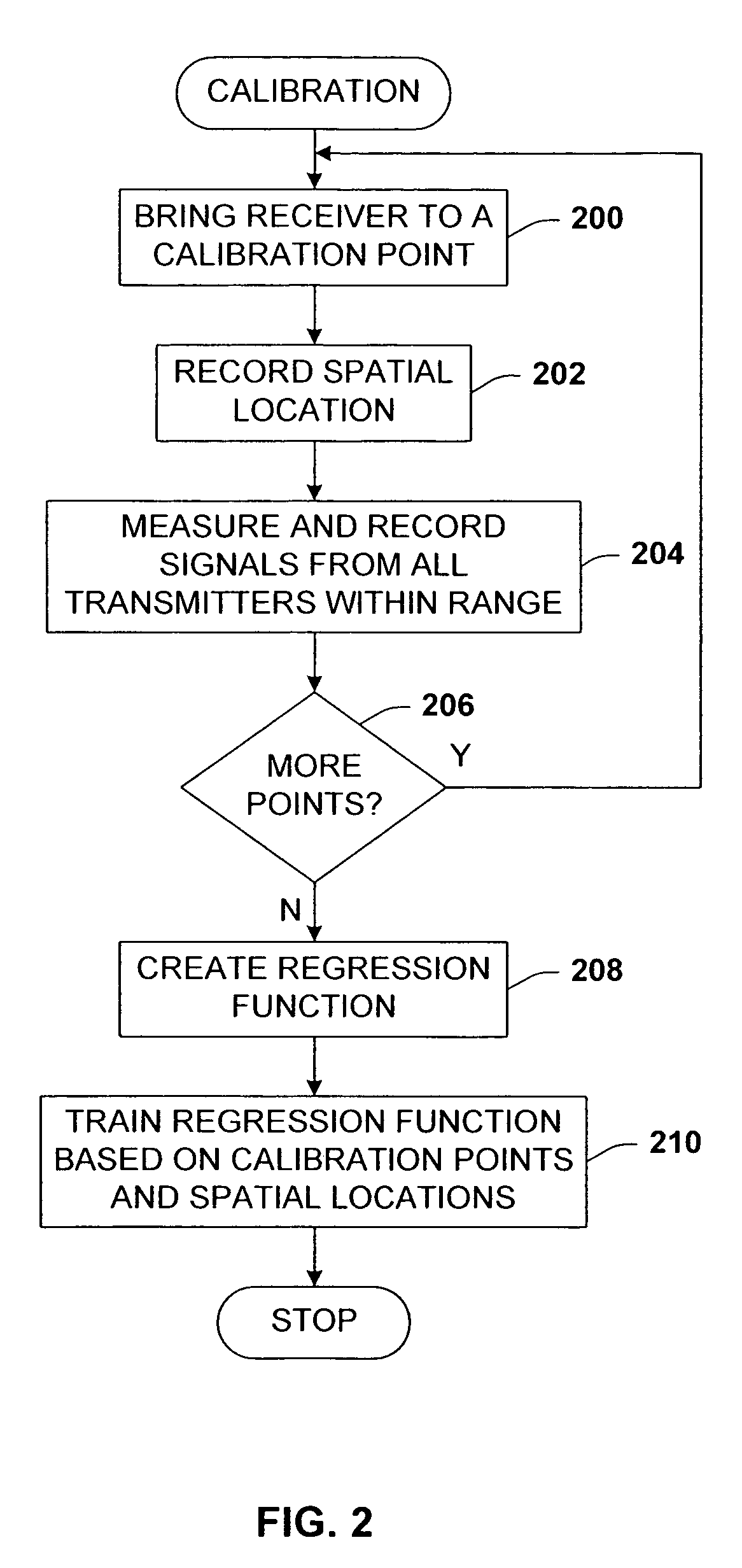
[0057]As indicated above, the location algorithm of the present invention works based on regression of signal strength training data taken from known room locations.

[0058]Referring now to FIG. 5, there is illustrated a layout of a typical office floor 500 of rooms 502 utilized for a sample application of the calibration process of the present invention. The floor 500 includes 132 rooms 502 of which 118 were accessible. The area of the floor 500 is approximately 2,680 square meters. The floor was taken to be region 100. The building maps of the floors were extracted both as polygon representations and bitmaps. The coordinates of all maps were expressed in actual floor coordinates in meters. The algorithm was evaluated on the one floor 500 with the 118 different rooms.

[0059]To study the problem of calibration effort, the amount of calibration data was reduced as if less time was spent in each room and as if certain rooms had been skipped. The 118 rooms were split into 137 sections, si...


PUM


Abstract

An architecture for minimizing calibration effort in an IEEE 802.11 device location measurement system. The calibration technique is based upon a regression function that produces adequately accurate location information as a function of signal strength regardless of gaps in the calibration data or minimally available data. The algorithm takes a set of signal strengths from known room locations in a building and generates a function giving (x,y) as a function of signal strength, which function may then be used for the estimation of new locations. Radial basis functions, which are simple to express and compute, are used for regression. The fact that the algorithm maps signal strength to continuous location makes it possible to skip rooms during calibration, yet still evaluate the location in those rooms.

Description

TECHNICAL FIELD[0001]This invention is related to IEEE 802.11 devices, and more specifically, to locating wireless devices using wireless signal strengths.BACKGROUND OF THE INVENTION[0002]Knowledge of locations of users and devices inside a building is an important prerequisite for location-based services and aspects of ubiquitous computing. One promising approach to determining location is through triangulation by measuring IEEE 802.11 wireless signal strengths of wireless devices. One of the most attractive features of an IEEE 802.11 location-based system is that it does not require any extra infrastructure beyond a wireless network that already exists in many buildings. This is in contrast to other person-tracking systems that employ active / passive badges and cameras, which in turn require installation and maintenance of extra equipment.[0003]Using an 802.11 wireless client as a location sensor (e.g., a portable computer as a receiver) is becoming increasingly popular way of enab...

Claims


Application Information

Patent Timeline
Patent Type & Authority Patents(United States)
IPC IPC(8): G01S3/02G01C17/00G01S5/02G01S19/09G01S19/46H04L12/28
CPCG01C21/206G01S5/0252H04W64/00H04W88/18H04W16/225H04W16/20G01S5/02528G01S5/021
Inventor KRUMM, JOHN C.PLATT, JOHN C.
Owner MICROSOFT TECH LICENSING LLC
Why Eureka
Try Eureka