Self-monitoring flow-through heater

Inactive Publication Date: 2006-01-31
GLOBAL FIA
View PDF2 Cites 5 Cited by
  • Summary
  • Abstract
  • Description
  • Claims
  • Application Information

AI Technical Summary

Benefits of technology

[0003]In general, the present invention provides a self-monitoring flow-through heater, comprising (a) a passageway providing a flow conduit; and (b) a wire disposed in the passageway, for heating and monitoring the temperature of a fluid flowing through the pas

Problems solved by technology

Polymeric tubes are poor conductors of heat; hence most reactors of this type have very poor utilization of thermal energy.

Method used


Image

  • Self-monitoring flow-through heater
  • Self-monitoring flow-through heater
  • Self-monitoring flow-through heater

Examples


example i

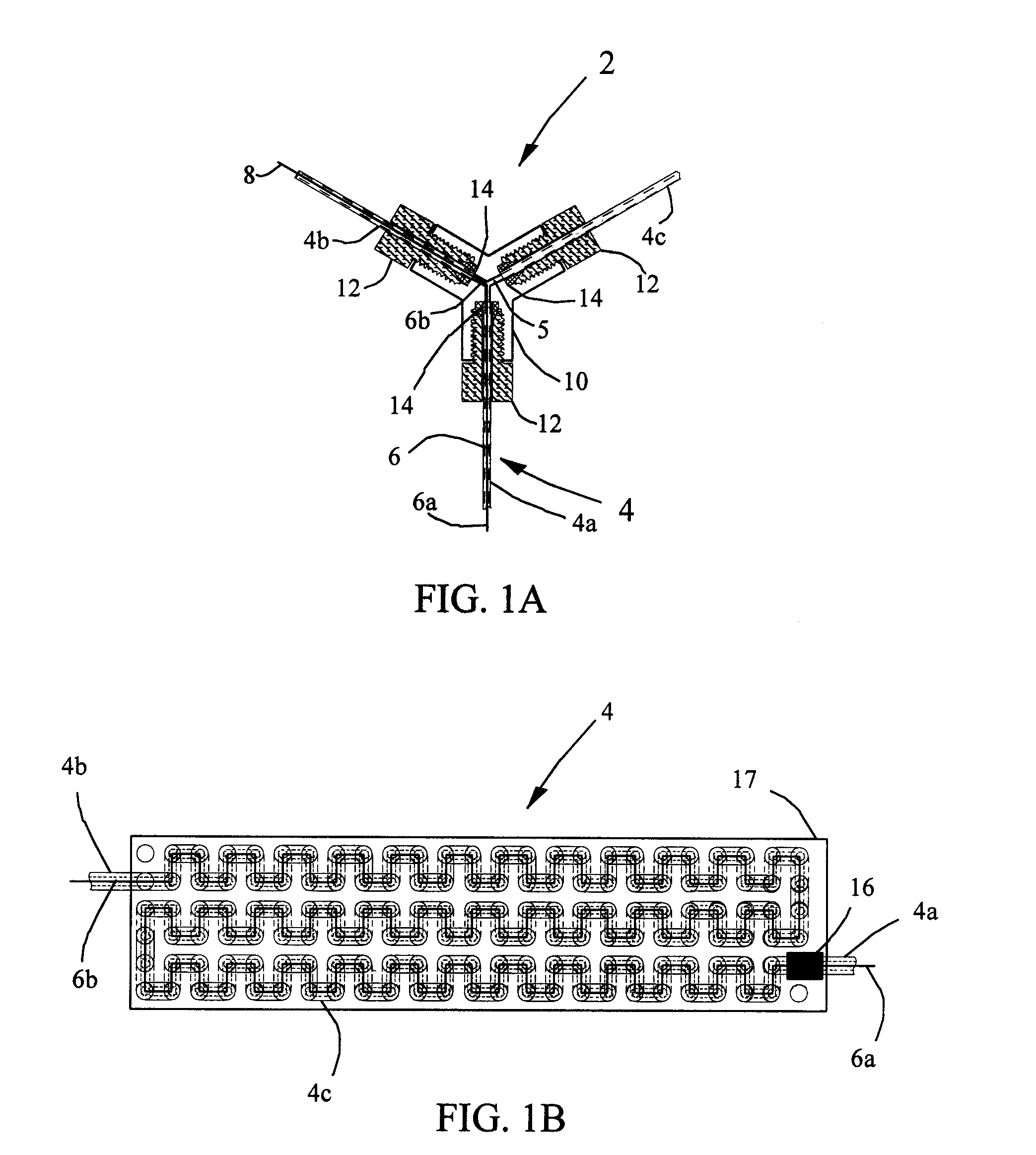
[0018 Results using the self-monitoring flow-through heater 2 for formaldehyde are shown in FIG. 3A. A water solution having a formaldehyde concentration of three micromoles per liter was automatically injected every ten minutes over a period of eighteen hours. The temperature as monitored by the external temperature sensor 16 is also plotted in FIG. 3A. Based on the mean resistance of the wire 6, insulated Balco wire made from an alloy comprising thirty percent iron and seventy percent nickel by weight, it was found that placing the sensor 16 at this point registers a temperature close to that of the mean temperature of the fluid 5 in the tube 4. The external temperature sensor 16 is placed near the fluid exit (not shown), where the temperature is the highest. However, because the external sensor 16 reads a lower temperature than the element of fluid 5 closest to the sensor 16, the sensor 16 reads a temperature closer to the mean temperature of the fluid 5 inside the tube 4. Both t...


PUM


Abstract

A self-monitoring flow-through heater. The heater has a wire inside a tube, and the wire heats and monitors the temperature of a fluid flowing through the tube. The wire has a high specific resistivity and a high temperature coefficient of resistance, so that monitoring the voltage across and / or the current flowing through the wire measures the mean temperature of the wire and of the fluid in the tube.

Description

BACKGROUND OF INVENTION[0001]The present invention relates to chemical analysis. More specifically, the invention relates to instrumental chemical analysis.[0002]In many experiments a flow-through heating arrangement is needed to reduce reaction time. Often the reaction conditions require inertness of the wetted material. Heated reactors based on polymeric tubing, notably polytetrafluoroethylene (PTFE), are the most common, and such reactors are typically used in a manner in which the reactors are immersed in a heated bath or an otherwise thermally conductive potting in which a heater and a temperature sensor are also immersed for heating and temperature control. Polymeric tubes are poor conductors of heat; hence most reactors of this type have very poor utilization of thermal energy. The present invention provides much more efficient energy utilization.SUMMARY OF INVENTION[0003]In general, the present invention provides a self-monitoring flow-through heater, comprising (a) a passag...

Claims


Application Information

Patent Timeline
IPC IPC(8): A45D20/10
CPCH05B3/80F24H9/2028
Inventor DASGUPTA, PURNENDU K.LOREE, ELLIS L.
Owner GLOBAL FIA
Why Eureka
Try Eureka