Preparation method of flexible strain sensor and flexible strain sensor

A strain sensor, flexible technology, applied in the direction of electric/magnetic solid deformation measurement, ion implantation plating, electromagnetic measurement device, etc., can solve the problems of graphene layer damage and pollution, graphene layer cannot be prepared, affect sensor performance, etc. Achieve the effect of reducing measurement error, reducing resistance temperature drift coefficient, and realizing mass production

Pending Publication Date: 2022-02-15
北京石墨烯技术研究院有限公司
View PDF8 Cites 0 Cited by
  • Summary
  • Abstract
  • Description
  • Claims
  • Application Information

AI Technical Summary

Problems solved by technology

The common problem of these methods is that the preparation conditions are harsh, such as the need for high temperature, easy agglomeration, and poor controllability, so it is impossible to directly prepare graphene layers on flexible substrates.
However, the graphene layer prepared by transfer is very easy to cause damage and contamination of the graphene layer, which ultimately affects the performance of the sensor.

Method used


Image

  • Preparation method of flexible strain sensor and flexible strain sensor
  • Preparation method of flexible strain sensor and flexible strain sensor
  • Preparation method of flexible strain sensor and flexible strain sensor

Examples


preparation example Construction

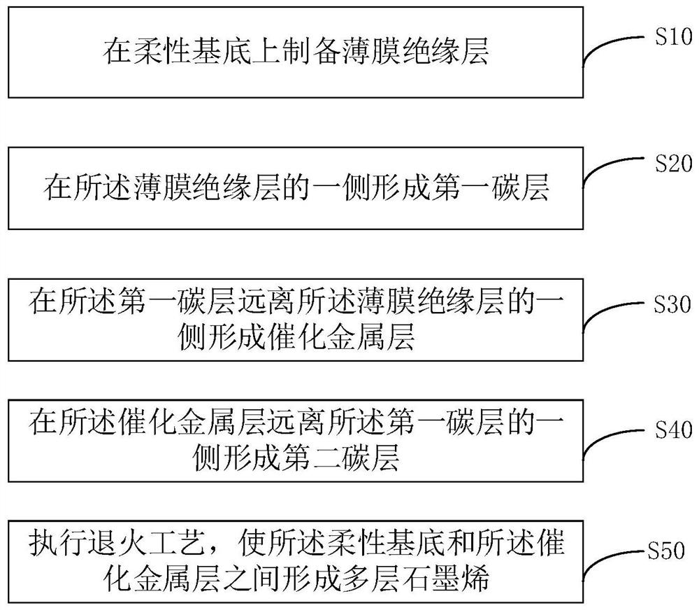
[0047] see figure 1 , an embodiment of the present invention provides a method for preparing a flexible strain sensor, comprising the following steps:

[0048] Step S10 , preparing a thin film insulating layer 20 on the flexible substrate 10 .

[0049] Step S20 , forming a first carbon layer 30 on one side of the insulating film layer 20 .

[0050] Step S30 , forming a catalytic metal layer 40 on a side of the first carbon layer 30 away from the thin film insulating layer 20 .

[0051] Step S40 , forming a second carbon layer 50 on a side of the catalytic metal layer 40 away from the first carbon layer 30 .

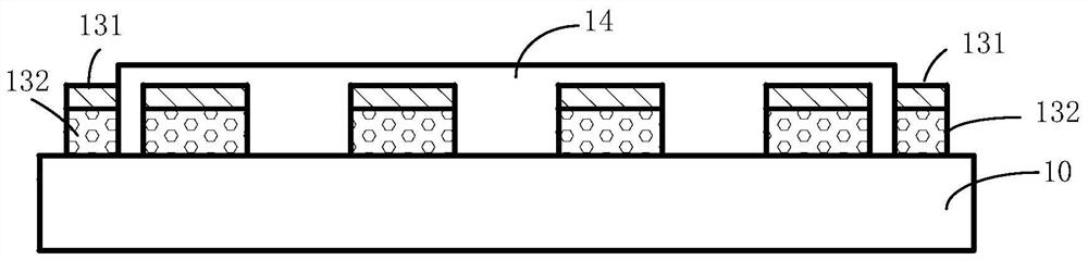
[0052] Step S50 , performing an annealing process to form multi-layer graphene between the flexible substrate 10 and the catalytic metal layer 40 .

[0053] Wherein, the first carbon layer, the catalytic metal layer and the second carbon layer have the same shape and are stacked in sequence, and the first carbon layer, the catalytic metal layer and the second carbon la...

Embodiment 1

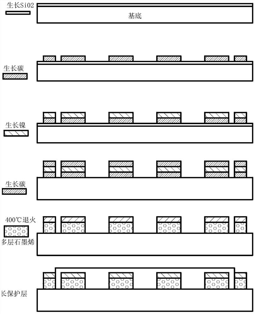
[0082] 1. Prepare a flexible substrate (with a thickness of 0.5 mm and a surface roughness below 200 nanometers). The substrate material is polyimide. The substrate is cleaned and dried by ultrasonic waves of acetone, ethanol, and deionized water in sequence.

[0083] 2. Put the flexible substrate into the deposition chamber of the RF magnetron sputtering deposition equipment to grow SiO 2 Thin film insulation. The process parameters are set as follows: choose Si target material, oxygen flow rate is 10sccm, working pressure is 1Pa, sputtering power is 500W, background vacuum degree is 1.0×10 -3 Pa, the sputtering time is 20min, and the growth temperature is 25°C. Finally, SiO 2 The thickness of the thin film insulating layer is 300nm.

[0084] 3. On SiO 2 The first mask plate is pasted on the thin film insulating layer, and it is put into the deposition chamber of the radio frequency magnetron sputtering deposition equipment to grow the first resistance grid structure and ...


PUM

PropertyMeasurementUnit
thicknessaaaaaaaaaa
thicknessaaaaaaaaaa
thicknessaaaaaaaaaa

Abstract

The invention relates to the technical field of strain sensor preparation, in particular to a preparation method of a flexible strain sensor and the flexible strain sensor. The preparation method comprises the following steps: preparing a thin film insulating layer on a flexible substrate; forming a first carbon layer on one side of the thin film insulating layer; forming a catalytic metal layer on one side, far away from the thin film insulating layer, of the first carbon layer; forming a second carbon layer on one side, far away from the first carbon layer, of the catalytic metal layer; carrying out an annealing process, so that multiple layers of graphene are formed between the flexible substrate and the catalytic metal layer; wherein the first carbon layer, the catalytic metal layer and the second carbon layer have the same shape and are stacked in sequence, and the first carbon layer, the catalytic metal layer and the second carbon layer integrally form a resistance grid and electrode connection structure.

Description

technical field [0001] The invention relates to the technical field of strain sensor preparation, in particular to a method for preparing a flexible strain sensor and the flexible strain sensor. Background technique [0002] Traditional metal film sensor resistors have the problems of high temperature coefficient, poor resistance heat dissipation and low sensitivity coefficient. As a semi-metallic conductor material, graphene has strong heat dissipation performance. Compared with traditional metal film sensors, graphene metal film sensors have higher sensitivity and larger measurement range. Graphene can reduce the resistance temperature drift coefficient of metal films, thereby reducing measurement errors. Improved measurement accuracy. However, the traditional methods of preparing graphene metal thin film sensors often use methods such as physical exfoliation, chemical vapor deposition, redox and other methods to pre-prepare to form a graphene layer, and then transfer it ...

Claims


Application Information

Patent Timeline
Patent Type & Authority Applications(China)
IPC IPC(8): C23C14/35C23C14/06C23C14/04C23C14/08C23C14/10C23C14/20C23C14/58C23C14/02G01B7/16
CPCC23C14/35C23C14/0605C23C14/042C23C14/205C23C14/5806C23C14/024C23C14/10C23C14/0036C23C14/081C23C14/0652G01B7/18
Inventor 李学瑞李炯利罗圭纳王刚于公奇王旭东
Owner 北京石墨烯技术研究院有限公司
Why Eureka
Try Eureka