Leakage power optimization for integrated circuits

a technology of integrated circuits and leakage power, applied in the field of leakage power optimization of integrated circuits, can solve the problems of gate leakage, exponential increase in subthreshold leakage, and increasing the dominant component of total power dissipation in leakage power, so as to reduce leakage power and achieve no area or performance penalty

Active Publication Date: 2006-01-31
XILINX INC
View PDF11 Cites 17 Cited by
  • Summary
  • Abstract
  • Description
  • Claims
  • Application Information

AI Technical Summary

Benefits of technology

[0009]In accordance with the present invention, a method for reducing leakage power in a system comprises determining the static probability for a signal in the system. If the static probability of the signal is in a high power range, then the signal is modified such that the static probability of the modified signal is in a low power range, and such that functionality of the system is not affected. In some embodiments, where the signal is a digital signal, modifying the signal comprises inverting the signal. In some embodiments, where the system comprises a programmable logic device, modifying the signal has no area or performance penalty.

Problems solved by technology

However, these improvements in technology have made leakage power an increasingly dominant component of total power dissipation.
Gate leakage, on the other hand, occurs due to tunneling current through the gate oxide of a transistor.
Reducing threshold voltage, however, leads to an exponential increase in subthreshold leakage.
This, however, leads to a considerable increase in gate leakage.
However, the programmability of FPGAs means that more transistors are typically needed to implement a given logic circuit, as compared with custom ASIC technologies.
Leakage power, however, is dissipated in both the used and the unused portions of an FPGA.
This further exacerbates the leakage power problem in FPGAS.
Each of these previous leakage reduction techniques has an associated cost impacting circuit area, delay, and / or fabrication cost.

Method used


Image

  • Leakage power optimization for integrated circuits
  • Leakage power optimization for integrated circuits
  • Leakage power optimization for integrated circuits

Examples


Embodiment Construction

[0020]The present invention is believed to be applicable to a variety of circuits and systems. The present invention has been found to be particularly applicable and beneficial for programmable logic devices, including field programmable gate arrays. While the present invention is not so limited, an appreciation of the present invention is presented by way of specific examples, such as with an FPGA comprising an array of configurable logic blocks having lookup tables for implementing logic functions.

[0021]In the following description, numerous specific details are set forth to provide a more thorough understanding of the present invention. However, it will be apparent to one ordinarily skilled in the art that the present invention can be practiced without these specific details. In other instances, well-known circuits and devices may be omitted or presented in abstract form in order to avoid obscuring the present invention.

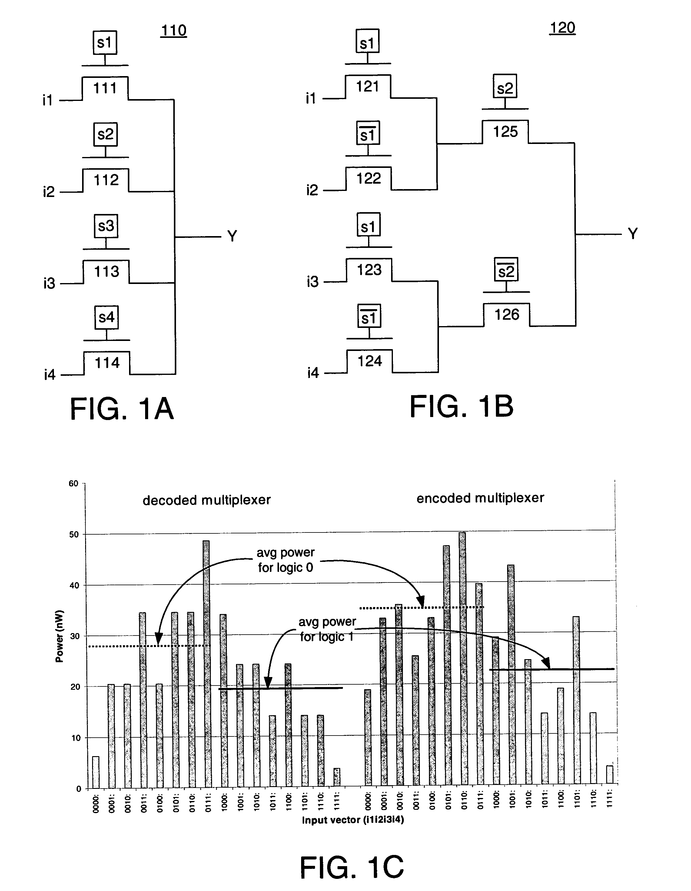
[0022]FIG. 1A shows an implementation of a 4-to-1 decoded mu...


PUM


Abstract

A method for reducing leakage power in a system comprises determining the static probability for a signal in the system. If the static probability of the signal is in a high power range, then the signal is modified such that the static probability of the modified signal is in a low power range, and such that functionality of the system is not affected. In some embodiments, where the signal is a digital signal, modifying the signal comprises inverting the signal. In some embodiments, where the system comprises a programmable logic device, modifying the signal has no area or performance penalty.

Description

FIELD OF THE INVENTION[0001]The invention relates to integrated circuits (ICs), and more particularly, to leakage power in ICs.BACKGROUND OF THE INVENTION[0002]Integrated circuits (ICs) continue to become smaller as technology continues to improve. However, these improvements in technology have made leakage power an increasingly dominant component of total power dissipation. Leakage power has two main forms in modern IC processes: subthreshold leakage and gate leakage. Subthreshold leakage occurs due to a non-zero current in a transistor between its source and drain terminals when the transistor is in an OFF state. Gate leakage, on the other hand, occurs due to tunneling current through the gate oxide of a transistor. Both forms of leakage have increased, as a proportion of total power, due to changes necessitated by the improving technology. For example, with each process generation, supply voltages are reduced. In order to mitigate performance degradations due to the reduced suppl...

Claims


Application Information

Patent Timeline
Patent Type & Authority Patents(United States)
IPC IPC(8): G06F17/50
CPCG06F17/504G06F17/5054G06F2217/78G06F30/3323G06F30/34G06F2119/06
Inventor ANDERSON, JASON H.NAJM, FARID N.
Owner XILINX INC
Why Eureka
Try Eureka