Optical link module

Inactive Publication Date: 2006-02-07
SUMITOMO ELECTRIC IND LTD
View PDF9 Cites 9 Cited by
  • Summary
  • Abstract
  • Description
  • Claims
  • Application Information

AI Technical Summary

Benefits of technology

[0007]It is an object of the present invention to provide an optical module that achieves a hig

Problems solved by technology

This reduces a produc

Method used


Image

  • Optical link module
  • Optical link module
  • Optical link module

Examples


Embodiment Construction

[0023]Embodiments of the present invention will be described in detail below with reference to the attached figures. In the description, the same symbols are assigned to the same elements without overlapping explanation.

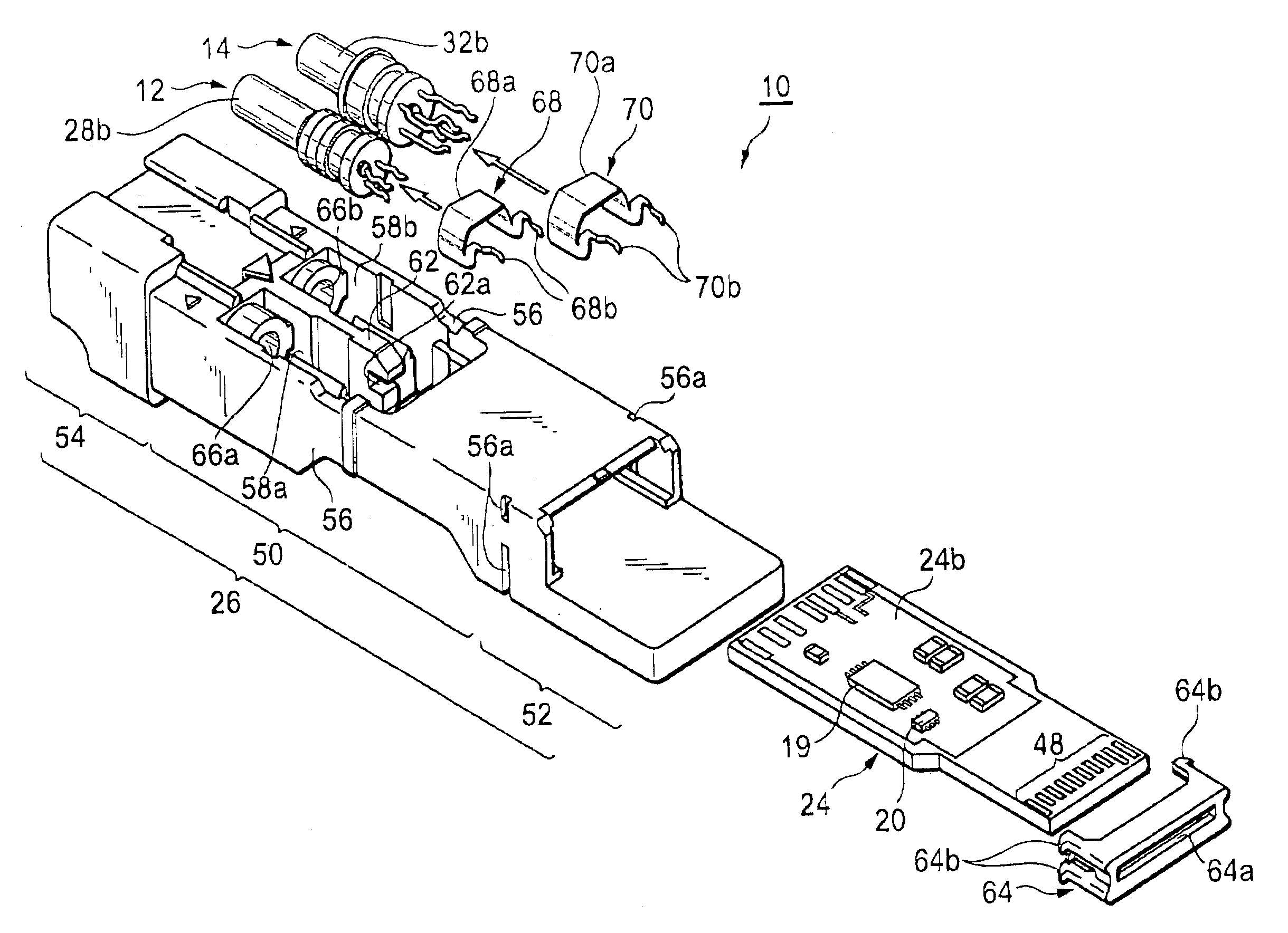
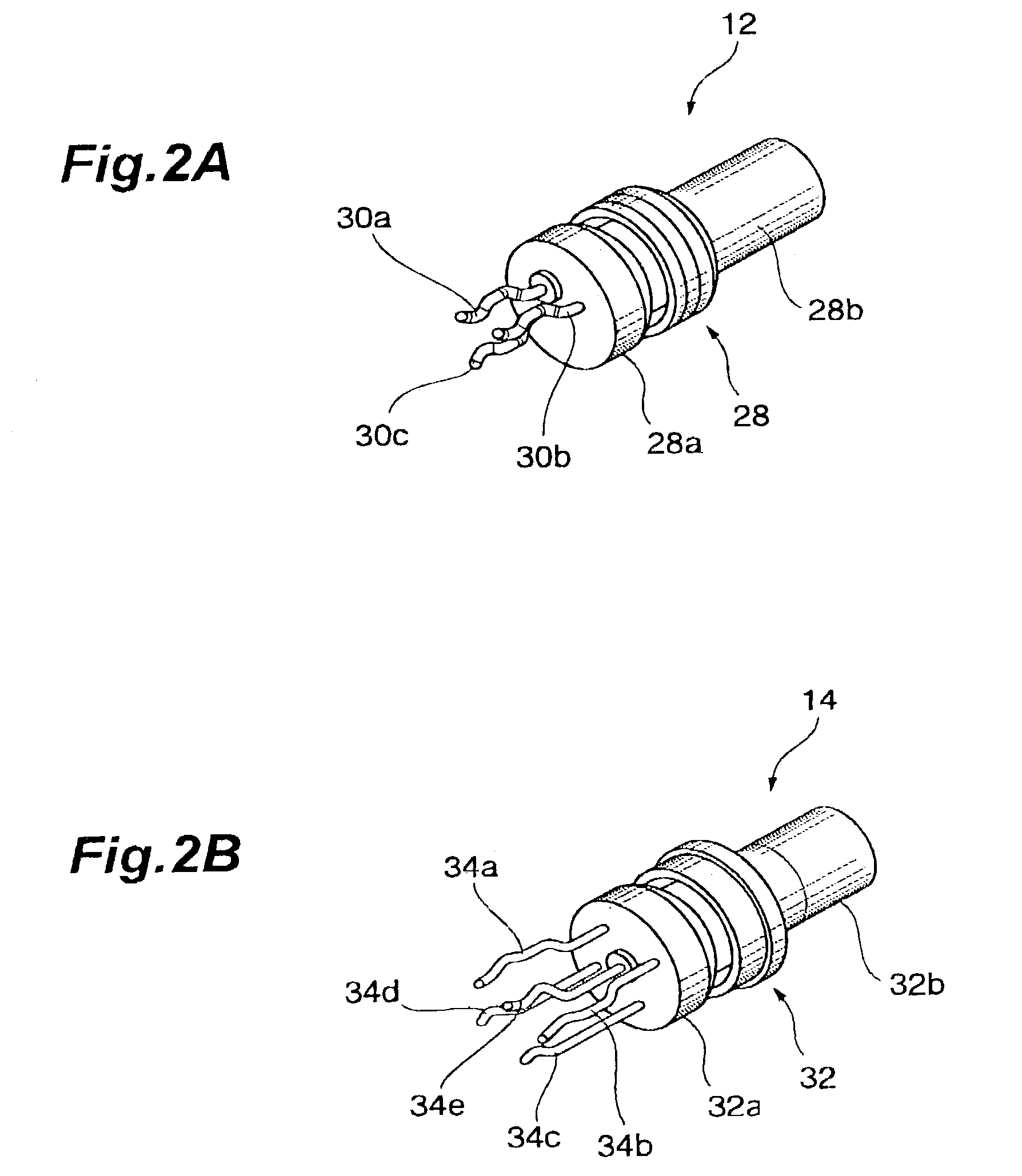
[0024]FIG. 1 is an exploded perspective view that illustrates the configuration of the optical link module according to the present embodiment. As shown in FIG. 1, the optical link module 10 comprises: a transmitting optical sub-assembly (TOSA) 12, a receiving optical sub-assembly (ROSA) 14, a plurality of electronic parts, a board 24 and a housing 26. The TOSA 12 has a package 28 and three lead pins 30a to 30c. A light-emitting element, such as a semiconductor laser diode, is mounted in the package. The lead pins disposed on a base 28a of the package 28 includes a first signal pin 30a in in-phase, a second signal pin 30b in out-phase and a signal pan 30c for monitoring. The signal in out-phase has an opposite phase to the signal in in-phase. The tip portions of the ...


PUM


Abstract

An optical link module comprises a transmitting optical sub-assembly (TOSA), a receiving optical subassembly (ROSA), a board and electronic parts. The electronic parts are necessary for wire-bonding to connect electronic thereto and mounted only on either the first surface or the second surface of the board.

Description

BACKGROUND OF THE INVENTION[0001]1. Field of the Invention[0002]The present invention relates to an optical link module.[0003]2. Related Prior Art[0004]Optical link modules are widely used in data links and in optical communication systems such as optical LAN, which uses light as an information transmitting means.[0005]As is shown in FIG. 5, a conventional optical link module 100 comprises a housing 102, and a board 106 disposed on the bottom surface 104 of the housing 102. A transmitting optical sub-assembly (TOSA) 108, and a receiving optical sub-assembly (ROSA) 108, electronic parts 110 are mounted on the board. The respective lead pins 112 of the TOSA 108 and the ROSA are bent to-up-and-down direction. When the TOSA and the ROSA are placed on the board 106, the lead pins 112 are inserted and soldered into through holes in the board 106.[0006]In the conventional module, a high degree of integration is achieved by mounting electronic parts utilizing both a front and a back surface...

Claims


Application Information

Patent Timeline
IPC IPC(8): G02B6/43G02B6/42H01L33/00H01L31/02H01S5/022H05K1/18
CPCG02B6/4246G02B6/4277H05K1/181H05K2203/1572H05K2203/049G02B6/4261G02B6/4284G02B6/428G02B6/4263G02B6/4274Y02P70/50
Inventor INUJIMA, TAKAYOSHIOKI, KAZUSHIGEKURASHIMA, HIROMITSUMURA, EIJI
Owner SUMITOMO ELECTRIC IND LTD
Why Eureka
Try Eureka