Pulse gasification and hot gas cleanup apparatus and process

a gasification and hot gas technology, applied in the direction of combustible gas production, combustible gas purification/modification, machines/engines, etc., can solve the problems of affecting the life of equipment, affecting the use of sorbents, and devices generally failing to remove smaller particulates from streams, etc., to facilitate the use of appropriate sorbents and promote acoustic agglomeration

Inactive Publication Date: 2006-02-14
MFG & TECH CONVERSION INT
View PDF25 Cites 62 Cited by
  • Summary
  • Abstract
  • Description
  • Claims
  • Application Information

AI Technical Summary

Benefits of technology

[0010]In accordance with one embodiment of the present invention, an apparatus and process for gasification of feedstocks (e.g., coal, coke, other solid fuels, heavy liquid hydrocarbons, slurries, and the like) with in-situ hot gas clean-up to generate clean, medium Btu gas is disclosed. In one particular embodiment, the process employs a pulsed gasification device that incorporates one or two stages of gasification. The process promotes acoustic agglomeration of particulates to aid in particulate collection using conventional separation apparatus, and facilitates the use of appropriate sorbents to capture gaseous pollutants in a sonic-enhanced environment. The apparatus may be employed in a variety of different configurations, such as combined cycle configurations with varying combinations of fuel cell, gas turbine and steam turbine for power generation, as well as in cogeneration configurations for combined heat and power production, for hydrogen production, for liquid fuels production, or for direct reduction of iron.
[0011]In one embodiment, for instance, the gasifier system includes a pulse combustion device for first-stage gasification, a U-tube arrangement for slag removal, a vertical entrained flow section for second-stage gasification, and primary and secondary cyclones for particulate capture. Oxygen and steam can be used as gasification agents to enhance the product gas heating value and, in turn, promote flame stability and turndown partial oxidation. For instance, partial oxidation can occur in the first stage while predominantly steam reforming processes can occur in the second stage.
[0012]In the second stage, sorbent particles are injected into a gas stream subjected to an intense acoustic field. The acoustic field serves to improve sorbent calcination by enhancing both gas film and intra-particle mass transfer rates. In addition, the sorbent particles act as dynamic filter foci, providing a high density of stagnant agglomerating centers for trapping finer entrained flyash fractions. A regenerate sorbent can be used for in-situ sulfur capture and a sulfur recovery unit may be included to generate a sulfur byproduct. The byproduct can be, for instance, ammonium sulfate or elemental sulfur or sulfuric acid.

Problems solved by technology

Because the gas stream running such systems can adversely impact on the life of the equipment, the gas stream should be substantially free of the particulate matter.
Although conventional particulate removal devices may be used to remove some of the larger solid particulate matter from combustion gas streams, these devices generally fail to remove the smaller particulates from the streams.
Similar problems also exist in many gas streams in which the particulate suspended matter originates from other than combustion.
However, while the operation in the combustion or fuel lean mode provided satisfactory and encouraging results, the process was constrained thermodynamically and presented various problems related to emissions control.
Specifically, the following limitations became apparent:Sulfur retention or calcium utilization decreases with an increase in operating temperature under oxidizing or fuel lean conditions.
This tends to limit the extent of decrease in the solids loading in cyclone exit flue gas.

Method used


Image

  • Pulse gasification and hot gas cleanup apparatus and process
  • Pulse gasification and hot gas cleanup apparatus and process
  • Pulse gasification and hot gas cleanup apparatus and process

Examples


Embodiment Construction

[0034]It is to be understood by one of ordinary skill in the art that the present discussion is a description of exemplary embodiments only, and is not intended as limiting the broader aspects of the present invention, which broader aspects are embodied in the exemplary construction.

[0035]The present invention is generally directed to an innovative pulse gasification system that overcomes many of the limitations of prior pulse gasification systems and may be configured to comply with stipulated new emissions target of one-tenth of NSPS. For example, in one embodiment, the system and process of the present invention can be configured to emit less than about 0.12 lb / MMBTU of sulfur dioxide, less than about 0.06 lb / MMBTU of nitrous oxides (NOx), and / or less than about 0.003 lb / MMBTU of particulates.

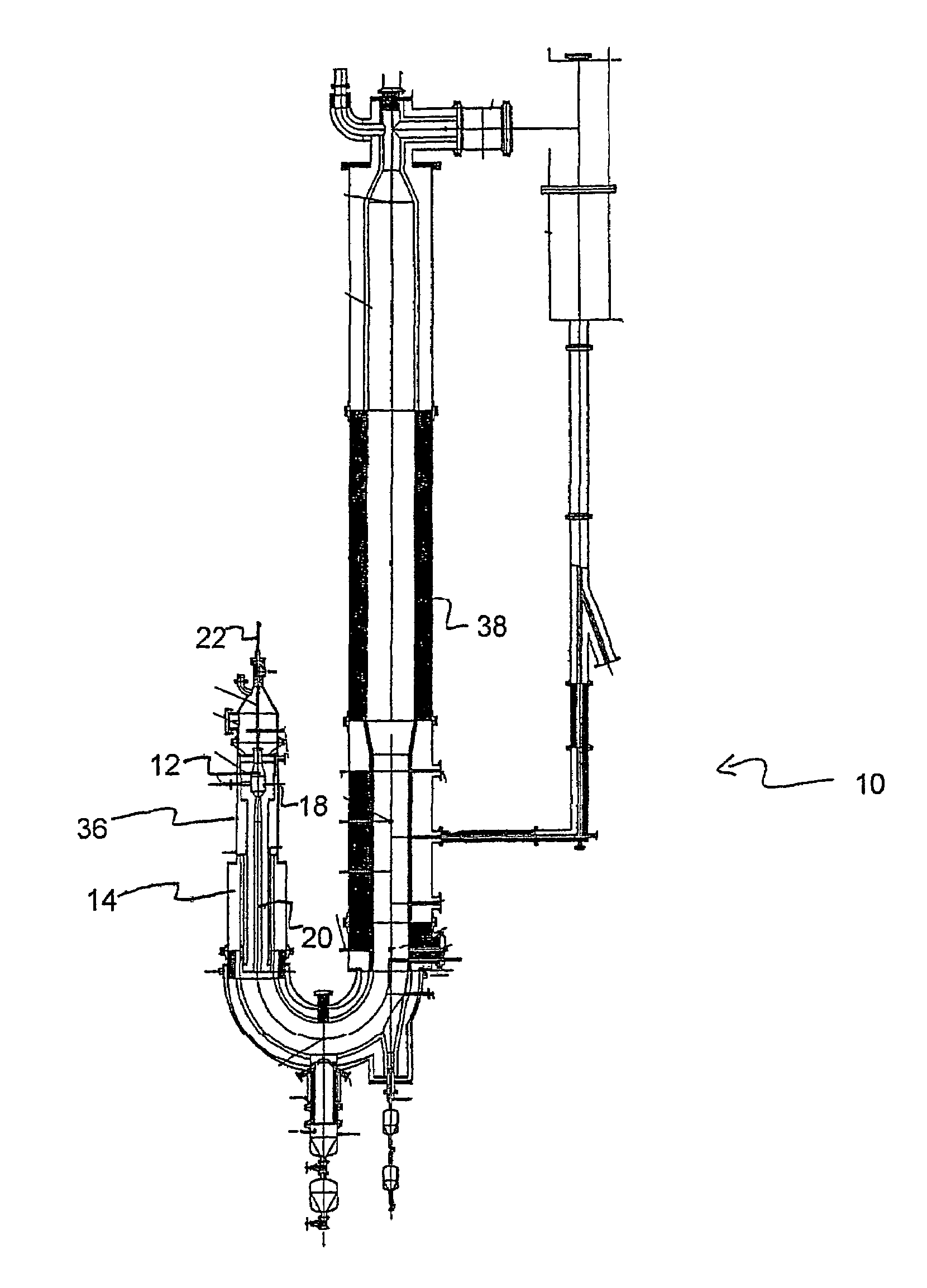
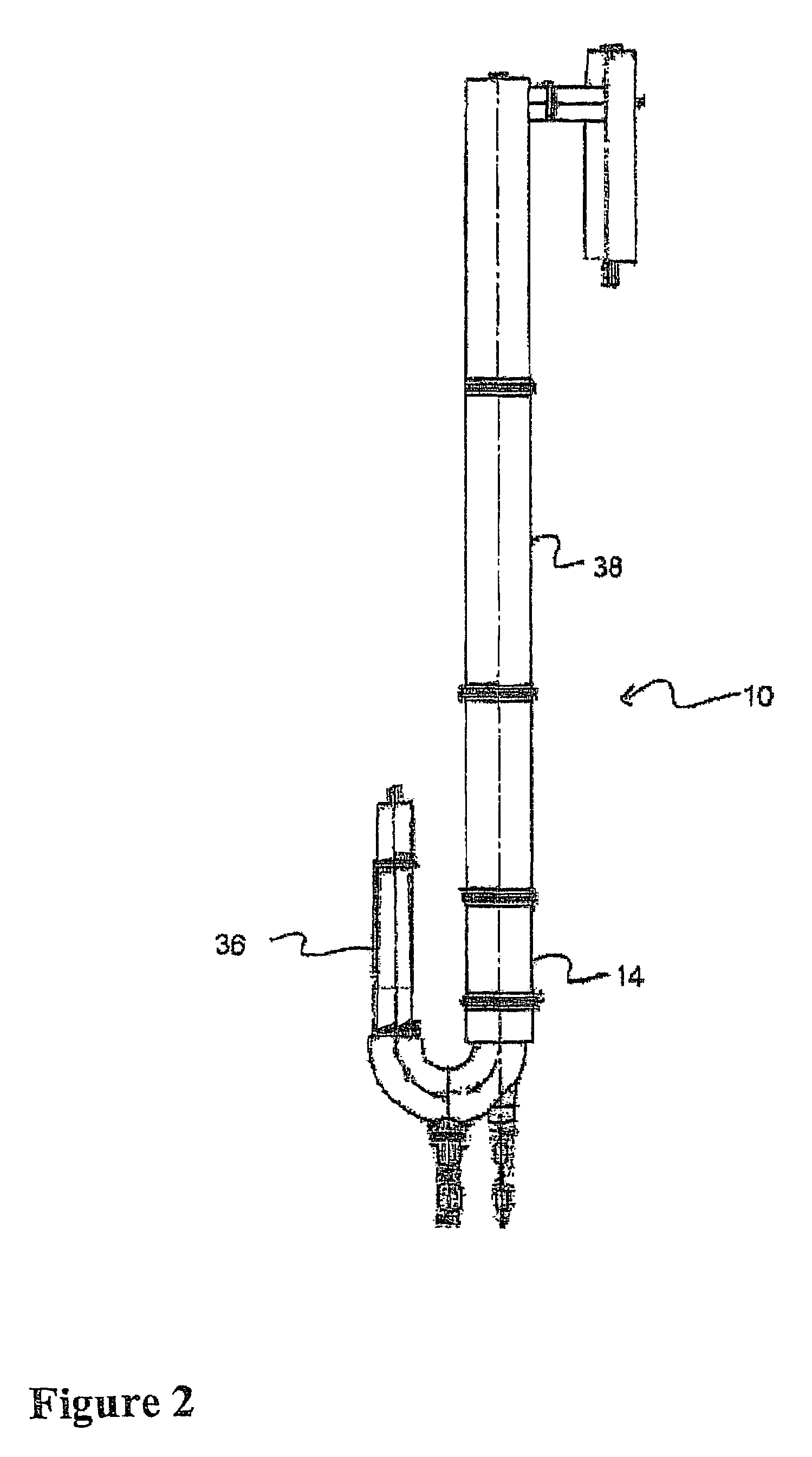
[0036]In one embodiment, the pulse gasifier system includes a pulse unit for first-stage gasification, a U-tube arrangement for slag removal, and may also include a vertical entrained flow s...


PUM

PropertyMeasurementUnit
exit temperatureaaaaaaaaaa
frequencyaaaaaaaaaa
exit temperatureaaaaaaaaaa

Abstract

A gasifier system and process comprises a pulse combustion device in communication with a fluid channel for producing a gas stream having heat or fuel value. The pulse combustion device is operated under sub-stoichiometric conditions such that combustion and steam reforming both occur in the fluid channel. The pulse combustion device also produces a pulsating combustion product stream and an acoustic pressure wave. The acoustic pressure wave serves to cause agglomeration of particles contained within the combustion stream for easy removal. In one embodiment, a sulfur capturing agent is injected into the fluid channel for not only removing sulfur from the combustion product stream but for also facilitating particle agglomeration. Ultimately, a gas stream containing hydrogen is produced that may be used in various processes, such as in the production of electricity.

Description

RELATED APPLICATIONS[0001]The present application is a divisional application and claims priority to U.S. patent application Ser. No. 10 / 445,289 filed on May 22, 2003 now U.S. Pat. No. 6,832,565, which claims priority to and is based upon a provisional patent application having application Ser. No. 60 / 382,302 filed on May 22, 2002.BACKGROUND OF THE INVENTION[0002]A major concern with the utilization of certain fuels in directly fired conventional power generation systems and other processes is the particulates produced by combustion of the fuels. These particulates remain in the combustion gas stream. Because the gas stream running such systems can adversely impact on the life of the equipment, the gas stream should be substantially free of the particulate matter. Although conventional particulate removal devices may be used to remove some of the larger solid particulate matter from combustion gas streams, these devices generally fail to remove the smaller particulates from the stre...

Claims


Application Information

Patent Timeline
Patent Type & Authority Patents(United States)
IPC IPC(8): F23B10/00B01D49/00B01D51/08B01D53/10C01B3/34C01B3/36C10J3/48C10J3/56F02B45/06F22B31/00F23J11/00F23J15/00
CPCB01D49/006B01D53/10C01B3/34C01B3/36C10J3/485C10J3/56C10J3/721C10K1/004C10K1/026B01D51/08Y02E20/16C01B2203/0216C01B2203/0255C01B2203/0425C01B2203/0485C01B2203/0844C01B2203/84C10J2200/09C10J2300/0906C10J2300/0916C10J2300/093C10J2300/0943C10J2300/0959C10J2300/0973C10J2300/0983C10J2300/1223C10J2300/1253C10J2300/1261C10J2300/1646C10J2300/165C10J2300/1659C10J2300/1675C10J2300/1838Y02E20/18C10J2300/0993Y02P20/129Y02P20/145
Inventor CHANDRAN, RAVIMANSOUR, MOMTAZ N.
Owner MFG & TECH CONVERSION INT
Why Eureka
Try Eureka