Tunable micro-lens array

a micro-lens array and optical lens technology, applied in the field of micro-lenses, can solve problems such as the expectation of propagation rather long distances

Inactive Publication Date: 2006-02-14
FUJITSU LTD
View PDF8 Cites 77 Cited by
  • Summary
  • Abstract
  • Description
  • Claims
  • Application Information

AI Technical Summary

Benefits of technology

[0007]Still another aspect of the present invention is directed to a method of reducing the temperature sensitivity of a lens system comprising a plurality of lens elements, at least one of the lens elements comprising thermo optical material, the method comprising choosing a desired beam width at a desired distance from the output of said lens system, determining the range of operating temperatures for said lens system, analyzing the relationship between the parameters of the lens system and the output beam width at said desired distance for a plurality of temperatures within said range of operating temperatures, wherein said parameters include the shape of the lens elements, the indices of refraction of the lens materials at each of said plurality of temperatures, and the nature of the interfaces between said lens elements, and based on said analysis, selecting parameters for said lens system which provide substantially said chosen beam width at said desired distance with the minimum amount of variability over said range of operating temperatures.
[0008]Another aspect of the present invention comprises a method of reducing the temperature sensitivity of a lens system comprising a plurality of lens elements, at least one of the lens elements comprising thermo optical material, comprising constructing a plurality of curves correlating the output beam width of the lens system at selected distances from the lens system with the temperature of the lens system, taking into account the indices of refraction of the materials used in the lens system, the shape of the lens elements used in the lens system, each of said curves have a minima whereat the temperature sensitivity of the lens system is relatively flat, and selecting a curve which has a minima in the vicinity of the desired operational parameters of the lens system, constructing a lens system associated with the selected curve.
[0009]Accordingly, it is an object of the present invention to provide a tunable micro-lens or array of tunable lenses using a thermo optical material so that the focal property of the lenses can be adjusted by controlling the temperature of the lenses.
[0011]A further object of the present invention is to provide a method of selecting the parameters of a lens incorporating thermo optical material such that the optical properties of the lens is relatively insensitive to temperature changes in the operating region.

Problems solved by technology

However, in such devices collimated beams are sometimes expected to propagate rather long distances without confinement in the direction parallel to the surface and perpendicular to the beam propagation.

Method used


Image

  • Tunable micro-lens array
  • Tunable micro-lens array
  • Tunable micro-lens array

Examples


Embodiment Construction

[0022]As described above, as recognized by the present inventors, there are a variety of reasons why its is desirable to use tunable micro-lenses and micro-lens arrays in various types of optical systems and devices. Changes in environmental conditions (e.g., temperature), light wavelength, polarization states, etc., over time can cause deviations in system or device performance. Other devices in the optical system may have requirements which vary over time. Likewise, manufacturing variability can cause differences in device performance which can be addressed by tuning the system.

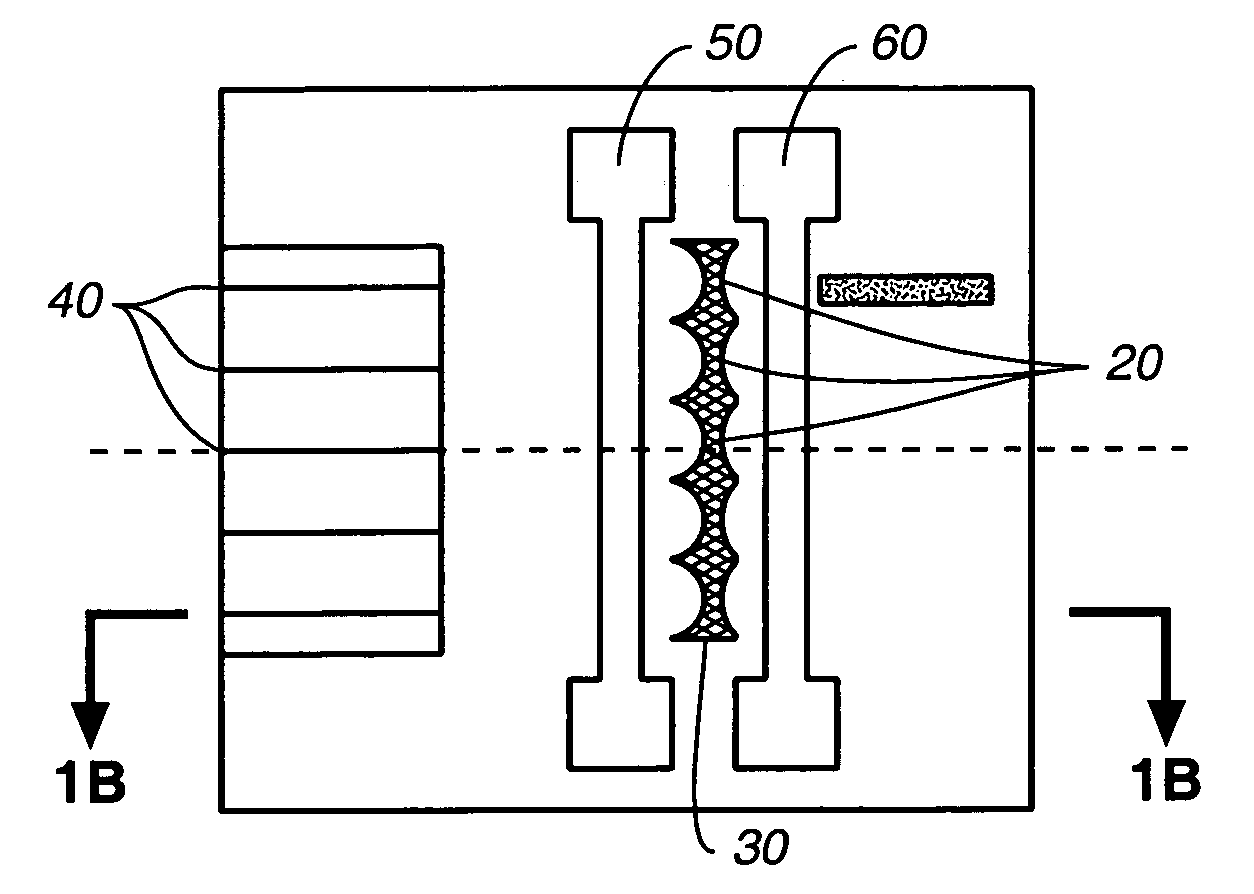
[0023]Some optical devices, such as switches, have arrays of closely packed input and output channels. Such devices require the ability to produce collimated light beams which traverse distances as great as 10–15 cm. The pitch of adjacent channels can be as small as 500 microns, requiring that the beam width be kept below 450 microns. Keeping beam widths within these limits requires cross-collimation rather...


PUM

PropertyMeasurementUnit
traverse distancesaaaaaaaaaa
widthaaaaaaaaaa
widthaaaaaaaaaa

Abstract

A tunable micro-lens and micro-lens array for use in optical communications are disclosed. The micro-lens uses thermo optical material and a temperature controller to adjust the temperature and, hence, the index of refraction of the thermo optical material. In one embodiment, a single temperature controller is used to maintain an array of micro-lenses at a desired temperature. In an alternate embodiment, the individual lenses in an array are separately tunable. The invention may be used with either 2D or 3D lenses, and is well suited for use with existing planar lightwave circuit (PLC) technology.

Description

FIELD OF THE INVENTION[0001]The present invention is directed to tunable optical lens designs and is more specifically directed to micro-lenses used in optical communications systems.BACKGROUND OF THE INVENTION[0002]Over the past decade considerable attention has been given to development of micro-optic lens arrays (MLA). Micro-optic lens arrays (also referred to as micro-lens arrays) have applications in many areas of optics, fiber communications and optical interconnects. With advances in dense wavelength division multiplexing (DWDM) networks, the need for multi-channel beam collimation and focusing has grown steadily. MLA structures may be employed for three-dimensional (3D) light beam collimation, for example, in 3D fiber array to fiber array connections or 3D microelectronic mechanical (MEM) optical switches. Two dimensional (2D) MLAs with light beam collimation, built using planar lightwave circuit (PLC) technology, are also widely used for planar optical devices. PLC devices ...

Claims


Application Information

Patent Timeline
Patent Type & Authority Patents(United States)
IPC IPC(8): G02B26/00G02B27/10G02B6/30B29D11/00G02B3/00G02B7/02G02F1/01
CPCG02B7/028G02B6/32G02B3/0081G02B3/0012G02B3/0068
Inventor GLEBOV, ALEXEIHUANG, LIDUYOKOUCHI, KISHIO
Owner FUJITSU LTD
Why Eureka
Try Eureka