Numerical control apparatus and CAM system

a control apparatus and cam system technology, applied in the field of processing systems, can solve the problems of system failure to maintain processing accuracy, speed may become far from the value instructed by the f code, and limited speed value, so as to achieve alleviate tool wear, and achieve the effect of achieving the optimal main spindle revolution

Inactive Publication Date: 2006-02-14
TOSHIBA MASCH CO LTD
View PDF7 Cites 10 Cited by
  • Summary
  • Abstract
  • Description
  • Claims
  • Application Information

AI Technical Summary

Benefits of technology

[0015]It is therefore an object of the invention to provide a numerical control apparatus capable of reliably obtaining an optimum main spindle revolution even under special relations of a tool and a workpiece, thereby alleviating wear of the tool and ensuring high-speed, high-accuracy processing, and a CAM system that can give appropriate information to the numerical control apparatus.
[0016]In the present invention, since information about the contact position between the tool and the workpiece is computed by the CAM system and added to the processing program, and the numerical control apparatus uses the information about the contact position contained in the processing program to control the revolution of the main spindle. Therefore, even under special positional relations between the tool and the workpiece, such as the moving direction of the tool being parallel to the inclined surface of the workpiece, it is ensured to obtain an optimum main spindle revolution, alleviate wearing of the tool, and realize high-speed, high-accuracy processing.

Problems solved by technology

However, if the tool is moved at a speed instructed by the F code, the system may fail to maintain the processing accuracy due to error factors such as a delay of a servo system.
However, in case a system has the above-mentioned function of automatically controlling the feeding speed in accordance with the form, if these values are instructed by the F code and the S code of the program, the speed value is limited, and even though the revolution of the main spindle is constant, the speed may become far from the value instructed by the F code.
However, since this function computes the contact position between the tool and the workpiece based on the moving direction of the tool instructed by the processing program, it cannot cope with changes of the contact position in particular cases.
However, since the optimum condition of combination of the main spindle revolution and the feeding speed changes variously depending on stiffness of the tool and the workpiece, number of blades of the tool, and so on, in case CAM instructs the main spindle revolution by way of the processing program, it is annoying that the processing program itself has to be re-output every time when the optimum condition changes.

Method used


Image

  • Numerical control apparatus and CAM system
  • Numerical control apparatus and CAM system
  • Numerical control apparatus and CAM system

Examples


first embodiment

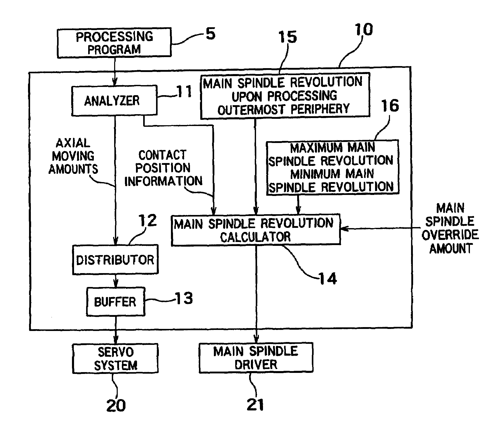
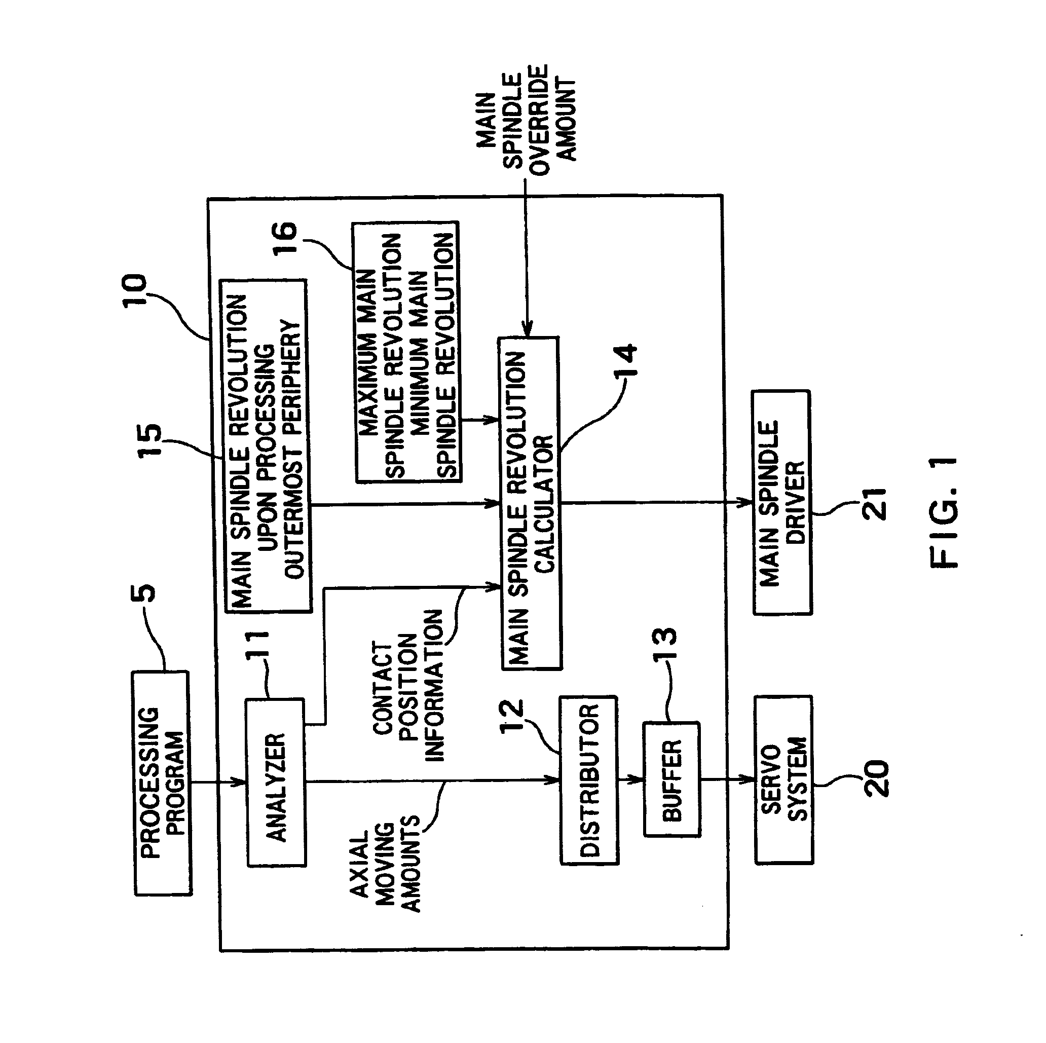
[0024]FIG. 1 is a block diagram that shows general configuration of a numerical control apparatus 10 according to the invention. In this embodiment, no instruction value for the main spindle revolution is instructed in the processing program.

[0025]The processing program 5 is sent to an analyzer 11 and analyzed there. The analyzer 11 extracts character strings such as X code, S code, G code, M code, and so on, from character strings in the processing program, and finds respective axial moving amounts. These axial moving amounts can be found, for example, as moving amounts along X, Y and Z axes from coordinates of start and terminal positions of processing. These amounts are found for each block.

[0026]Moving amount on each axis are converted by a distributor 12 to a movement instruction of each axis, and sent to a servo system of each axis via a buffer 13.

[0027]On the other hand, the analyzer 11 outputs information about a contact position as well.

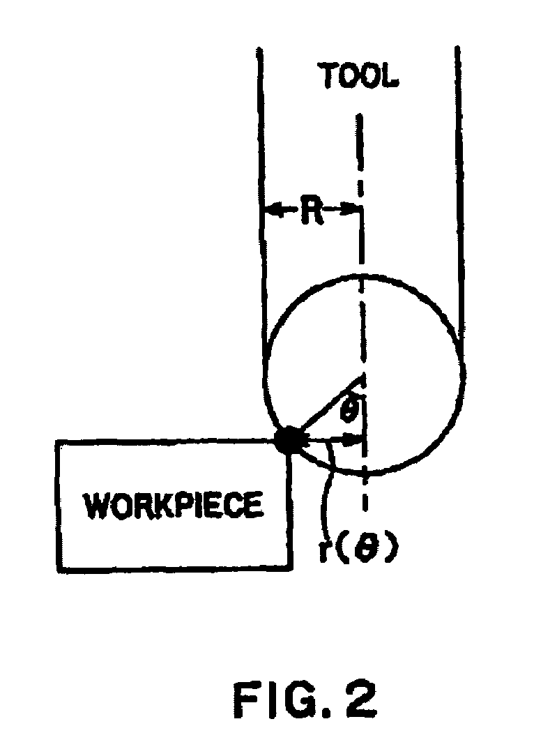
[0028]FIG. 2 is an explanatory diagra...

second embodiment

[0039]FIG. 3 is a block diagram that shows general configuration of a numerical control apparatus 30 according to the invention. Here is assumed again that no instructions value for the main spindle revolution is described in the processing program.

[0040]The processing program 5 is sent to an analyzer 31 and analyzed there. The analyzer 31 extracts character strings such as X code, S code, G code, M code, and so on, from character strings in the processing program, and finds moving amounts on respective axes. Procedures for finding moving amounts on respective axes are the same as those of the first embodiment.

[0041]An instruction feeding speed and information about a contact position obtained by the procedure shown in FIG. 2 as well are output from the analyzer 31, and they are sent to a target feeding speed calculator.

[0042]Axial moving amounts are sent to a form estimator 32, and a moving form is found. Decision of the moving form relies on determining whether it is a corner or a...


PUM

PropertyMeasurementUnit
radiusaaaaaaaaaa
tangential speedaaaaaaaaaa
speedaaaaaaaaaa

Abstract

Upon analyzing a processing program (5) in an analyzer (11, 31), a numerical control apparatus extracts information about a contact position between a tool and a workpiece, and based on the information, it calculates a main spindle revolution instruction value in a main spindle revolution calculator 14, 38). In a CAM system, information about the contact position between the tool and the workpiece to be supplied to the numerical control apparatus is calculated and added to the processing program.

Description

BACKGROUND OF THE INVENTION[0001]1. Field of the Invention[0002]This invention relates to a processing system suitable for accurately processing a free-form surface at a high speed, and more particularly, to a numerical control apparatus for controlling a main spindle revolution on instructions of a processing program and a CAM system for adding tool contact positional information to a processing program.[0003]2. Description of Related Art[0004]In a numerical control apparatus suitable for accurately processing a free-form surface at a high speed, the moving path of a tool is instructed by a processing program, and the moving speed of the tool along the path is also instructed by marking an F code in the processing program. However, if the tool is moved at a speed instructed by the F code, the system may fail to maintain the processing accuracy due to error factors such as a delay of a servo system.[0005]As a measure of preventing such disadvantages, some of recent NC apparatuses fo...

Claims


Application Information

Patent Timeline
Patent Type & Authority Patents(United States)
IPC IPC(8): G06F19/00B23Q15/12B23Q15/00G05B19/404G05B19/4093G05B19/416
CPCG05B19/4163Y10T409/300896G05B2219/49077G05B2219/35158B23Q15/00
Inventor MATSUMOTO, ICHIROFUJITA, JUN
Owner TOSHIBA MASCH CO LTD
Why Eureka
Try Eureka