Combined pressure and temperature transducer

a technology of pressure transducer and temperature transducer, which is applied in the direction of instruments, heat measurement, measurement devices, etc., can solve the problems of not being suitable for use with high temperature fluids, and achieve the effect of good dynamic response, fast and accura

Active Publication Date: 2006-02-21
SENSATA TECHNOLOGIES INC
View PDF2 Cites 94 Cited by
  • Summary
  • Abstract
  • Description
  • Claims
  • Application Information

AI Technical Summary

Benefits of technology

[0006]It is an object of the present invention to provide a condition sensing transducer which can be used with high temperature fluids, for example, up to 180 degrees C. Another object is the provision of a transducer which can monitor both pressure and temperature. Yet another object of the present invention is the provision of a combined pressure and temperature transducer having good dynamic response, both fast and accurate.

Problems solved by technology

Transducers made in accordance with the noted patent are highly effective and are widely used; however, they are not suitable for use with high temperature fluids, for example fluids at temperatures of up to 180 degrees C.

Method used


Image

  • Combined pressure and temperature transducer
  • Combined pressure and temperature transducer
  • Combined pressure and temperature transducer

Examples


Embodiment Construction

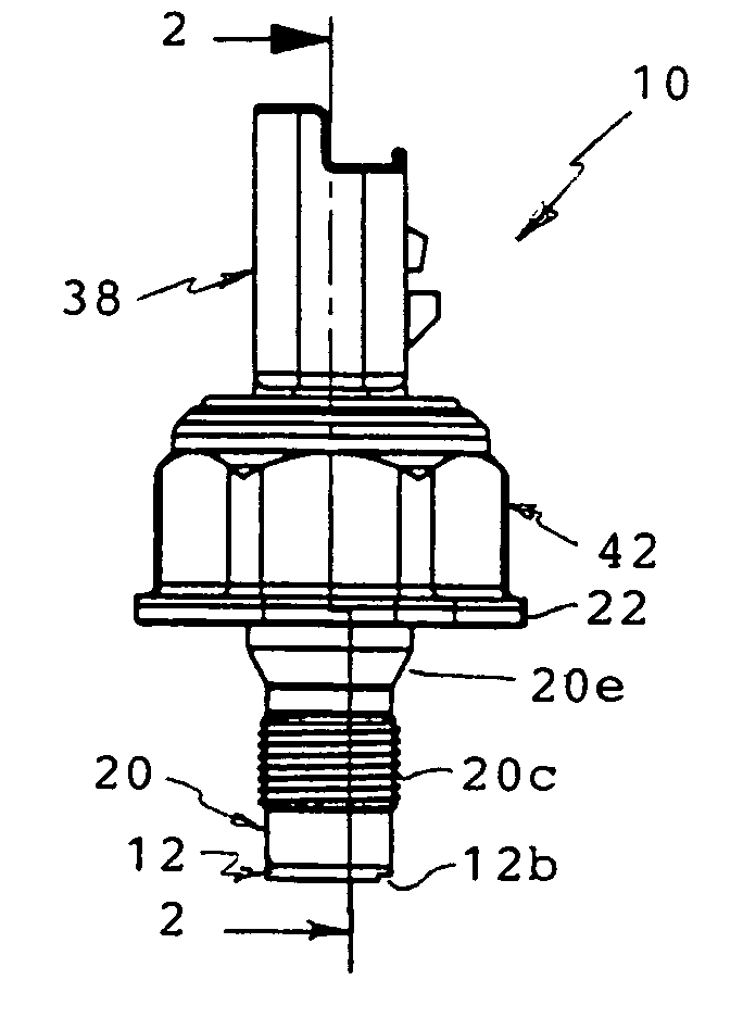
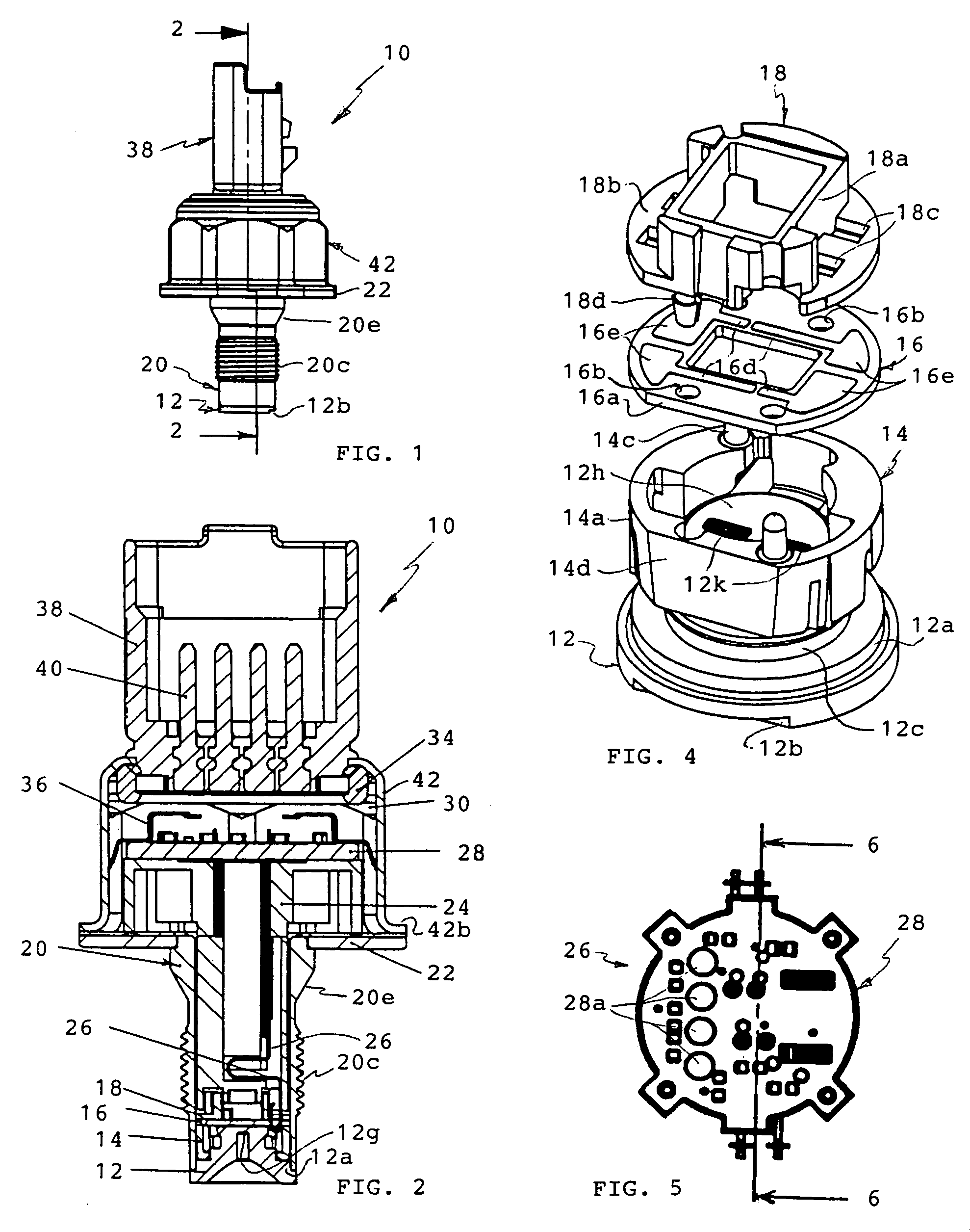
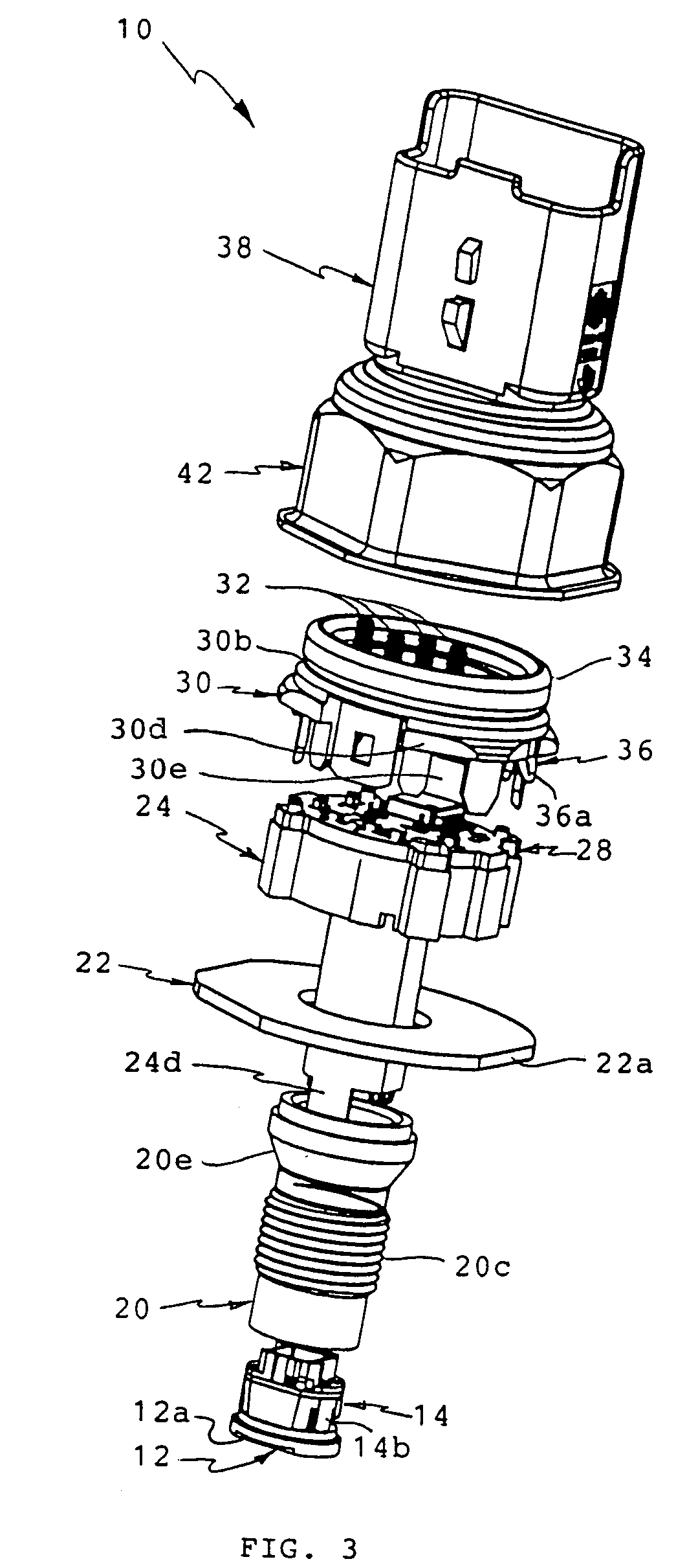
[0029]A combination pressure and temperature transducer 10 made in accordance with the preferred embodiment of the invention is shown in FIGS. 1–3. A sensing element 12, see in particular FIGS. 4 and 9–13, formed of suitable material such as stainless steel, is mounted at one end or tip of the transducer and is generally cylindrical for receipt in the end of a probe comprising a threaded pipe 20 formed of suitable material, desirably the same as that of sensing element 12. Sensing element 12 is formed with a cylindrical seating ridge 12a and a flat 12b on its outer periphery to facilitate providing a selected angular orientation. A reduced diameter, axially extending portion 12c is formed with an alignment flat 12d on its periphery and a radially, outwardly extending lip 12e for receipt of a lower support ring catch 14b, to be discussed. Sensing element 12 is formed with a cavity 12f defining a flat diaphragm 12g. The upper surface 12h, relative to the orientation in the drawings, h...


PUM

PropertyMeasurementUnit
temperatureaaaaaaaaaa
pressure sensitiveaaaaaaaaaa
electricalaaaaaaaaaa

Abstract

A combined pressure and temperature transducer (10) particularly adapted for high temperature fluids has a sensing element assembly mounted at the tip of a tubular probe (20) which is arranged for placement in a fluid flow path. A sensing element (12) includes a pressure responsive diaphragm (12g) closing the open end of the tubular probe and being provided with piezo-resistive gauge elements bonded to the diaphragm. Wires are bonded between the gauge elements and a first, heat resistant, printed circuit board (PCB). The first PCB, together with the piezo-resistive elements, form a Wheatstone bridge. An inner connector (26) mounts elongated, axial stress absorbing contacts connecting the first PCB at one end of the inner connector with a second printed circuit board (PCB) mounted at the opposite end of the inner connector physically removed from the sensing element and first PCB and away from the fluid flow path. The second PCB mounts signal conditioning and amplifying electronics. An outer connector (38) and housing (42) mounts the second PCB and provides an electrical interface with transducer.

Description

[0001]Benefit is claimed under 35 USC Section 119 (e) (1) of U.S. Provisional Application No. 60 / 648,682, filed Jan. 31, 2005.FIELD OF THE INVENTION[0002]This invention relates generally to a combined pressure and temperature transducer and more particularly to such transducers using strain gauge technology for sensing both temperature and pressure change to produce a signal related to such change and employing electronics for processing and amplifying the signal.BACKGROUND OF THE INVENTION[0003]An example of a prior art pressure transducer using strain gauge technology of the type with which the invention is concerned is disclosed and claimed in U.S. Pat. No. 6,742,395, which issued Jun. 1, 2004 to the assignee of the present invention, the subject matter of which is incorporated herein by this reference. In that patent, a transducer is described having a tubular port fitting formed with a fluid receiving opening at one end and a closed, integrally formed diaphragm at an opposite e...

Claims


Application Information

Patent Timeline
Patent Type & Authority Patents(United States)
IPC IPC(8): G01L19/04
CPCG01K1/08G01L9/0055G01L19/0092G01L19/142G01L19/0084G01L19/148G01L19/0038
Inventor ZWOLLO, CRIS RUIZGENNISSEN, PAULAPPELO, ROGER M.
Owner SENSATA TECHNOLOGIES INC
Why Eureka
Try Eureka