Cooling system for vehicle

Active Publication Date: 2006-02-21
DENSO CORP
View PDF16 Cites 16 Cited by
  • Summary
  • Abstract
  • Description
  • Claims
  • Application Information

AI Technical Summary

Benefits of technology

[0007]The present invention is made in view of the foregoing matters, and it is an object of the present invention to provide a cooling system capable of reducing its power consumption or restricting an increase in its power consumption.
[0009]Accordingly, the cooling fluid can be circulated without requiring an operation of a pump. Therefore, power consumption of the cooling system is reduced or an increase in power consumption of the cooling system is restricted. When the pump is provided in the cooling fluid circuit, an operation of the pump is controlled in accordance with the amount of heat generated from the heating element. Because a circulation rate of the cooling fluid by the pump operation is reduced, power consumption of the pump is reduced.

Problems solved by technology

Therefore, power consumption of the cooling system is reduced or an increase in power consumption of the cooling system is restricted.

Method used


Image

  • Cooling system for vehicle
  • Cooling system for vehicle
  • Cooling system for vehicle

Examples


first embodiment

[0017](First Embodiment)

[0018]A cooling system of the present invention is employed to hybrid vehicles, which is driven by an internal combustion engine and an electric motor. Especially, the cooling system of the embodiment is employed to a hybrid vehicle, which is driven by automatically selecting one of an engine driving mode, an electric motor driving mode and an engine and electric motor combination mode, according to a driving condition.

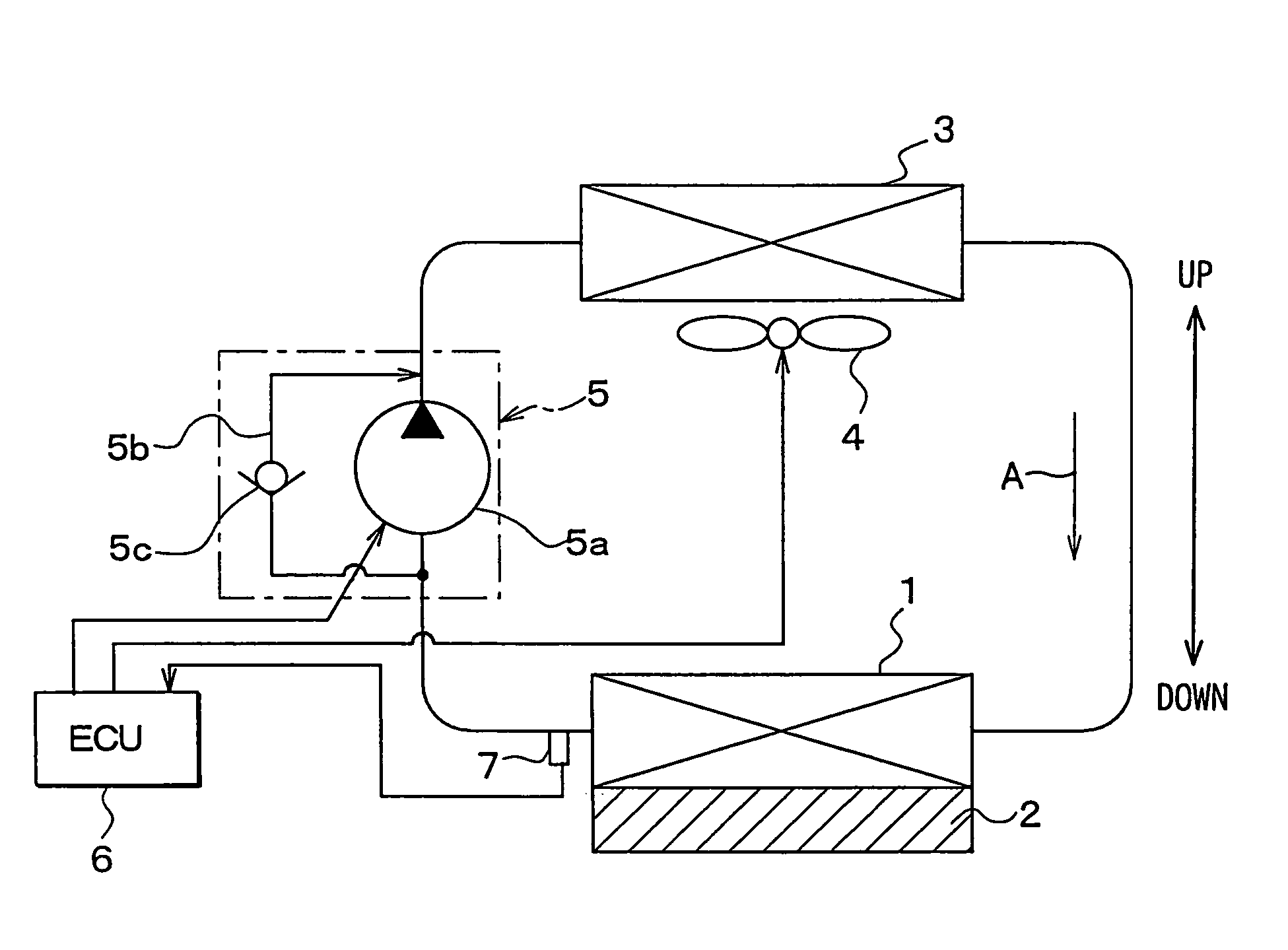
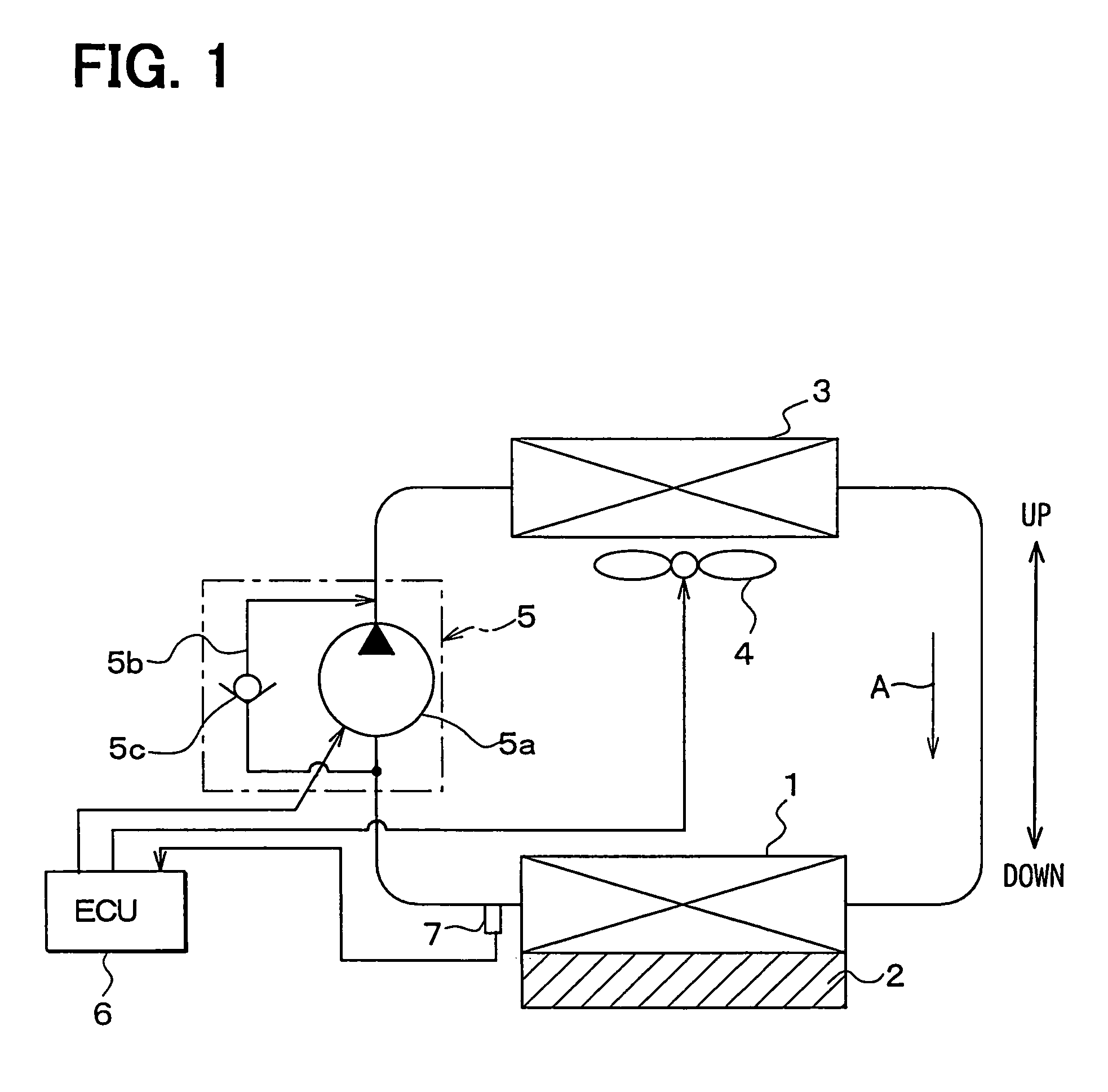
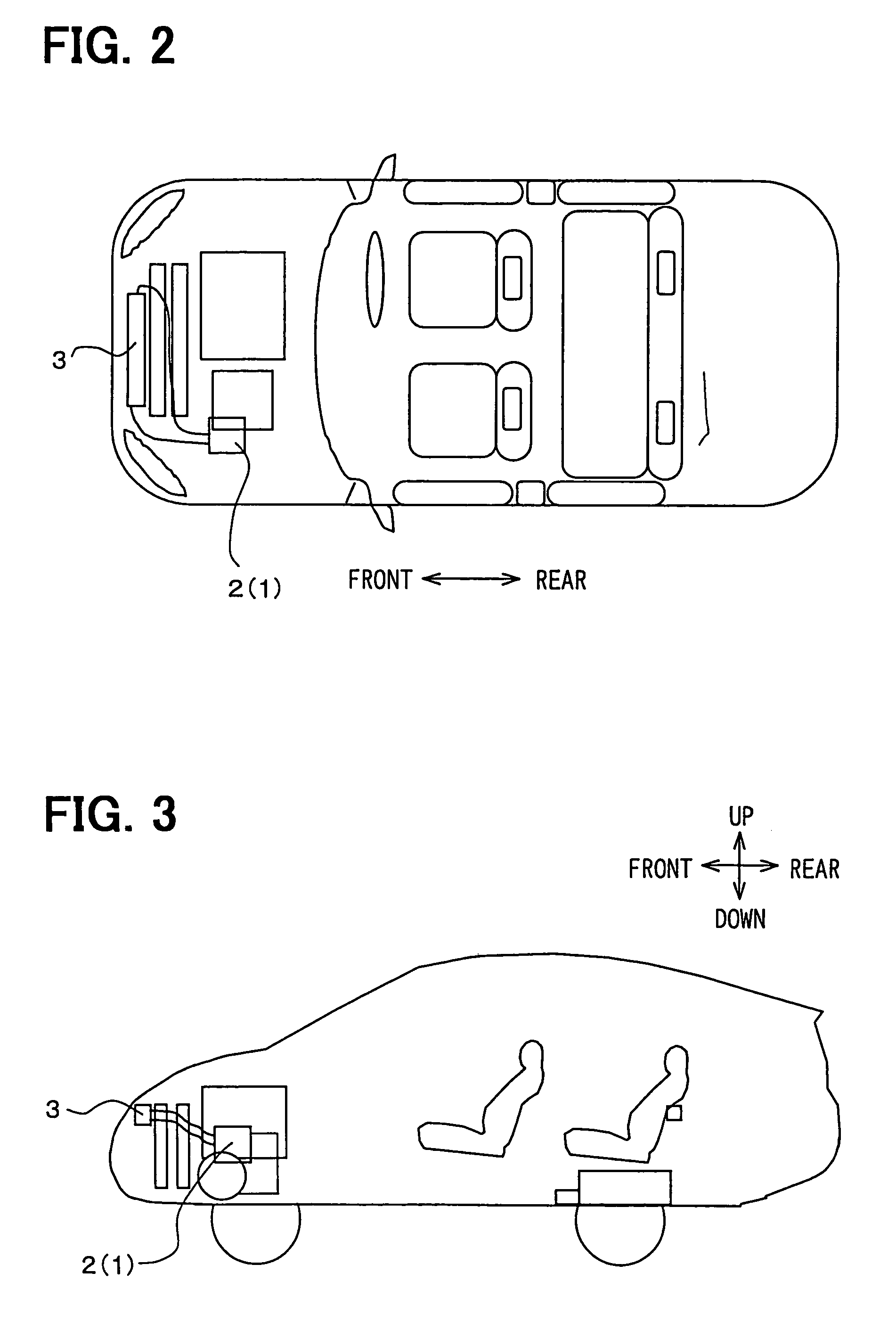
[0019]As shown in FIGS. 1 to 3, the cooling system of the embodiment has a heat sink 1, a radiator 3, a blower 4, a pump device 5, an electric control unit (ECU) 6 and a sensor 7. The heat sink 1 is provided as a heat exchanger to absorb a waste heat generated from a driving electric circuit 2 that supplies a driving current to an electric motor for driving. The driving electric circuit 2 is a heating element and includes an inverter circuit supplying the driving current and the like. The amount of the waste heat generated by the driving electr...

second embodiment

[0037](Second Embodiment)

[0038]In the first embodiment, the on and off operation of the blower 4 is performed with reference to the predetermined first level T1 as a threshold level. In the second embodiment, as shown in FIG. 5, an air blowing level of the blower 4 is increased stepwise from a minimum level to a maximum level with an increase in the amount of heat, that is, with the increase in the detected temperature T. Also, when the air blowing level of the blower 4 is lower than the maximum level, the pump portion 5a is stopped. Even when the air blowing level of the blower 4 is on the maximum level, if the detected temperature T is higher than a predetermined temperature, the circulation rate of the cooling water by the pump portion 5a is increased stepwise in accordance with the increase in the detected temperature T. Accordingly, the power consumption of the blower 4 and the pump device 5 are effectively reduced.

[0039]In the second embodiment, the cooling water circulation r...


PUM


Abstract

In a cooling system for cooling a heating element mounted in a vehicle, a radiator is located at a position higher than a heat sink, which absorbs heat from the heating element. When the amount of heat generated from the heating element, which is detected by a sensor, is greater than a predetermined first value, a blower is operated. Further, when the detected amount of heat is greater than a predetermined second value that is higher than the predetermined first value, a pump is operated. When the detected amount of heat is equal to or less than the predetermined first value, the pump is stopped and the cooling water is circulated by a principle of heat siphon. Accordingly, power consumption of the pump is reduced. Further, power consumption of the cooling system is reduced or an increase in power consumption of the cooling system is restricted.

Description

CROSS REFERENCE TO RELATED APPLICATION[0001]This application is based on Japanese Patent Application No. 2003-147959 filed on May 26, 2003, the disclosure of which is incorporated herein by reference.FIELD OF THE INVENTION[0002]The present invention relates to a cooling system for a vehicle, which is suitable for use in a hybrid vehicle driven by a combination of an electric motor and an internal combustion engine.BACKGROUND OF THE INVENTION[0003]In previous hybrid vehicles, power consumption of an electric motor for driving is generally smaller than that of an engine. Therefore, the amount of heat generated from such as the driving electric motor or a driving electric circuit for driving the driving electric motor, including an inverter circuit, is generally small. Accordingly, a heat radiating capacity required to a cooling system for such vehicles is not so large.[0004]In recent years, however, the hybrid vehicles are required to have a driving performance or an accelerating perf...

Claims


Application Information

Patent Timeline
IPC IPC(8): F28F7/00F01P7/14F28D15/00B60K6/20B60K11/04B60K11/02B60L1/02B60L15/00F01P3/12F01P3/18F01P7/16F25B1/06
CPCB60L1/02B60K11/02B60K6/26B60K2001/003
Inventor MORISHITA, YUSUKEINOUE, YOSHIMITSU
Owner DENSO CORP
Why Eureka
Try Eureka