Illumination device, liquid crystal device, and electronic apparatus

a liquid crystal device and liquid crystal technology, applied in lighting and heating apparatus, planar/plate-like light guides, instruments, etc., can solve problems such as areas a that are recognized by observers as excessively bright, and achieve the effect of preventing local high-luminance areas, and suppressing local high-luminance areas

Inactive Publication Date: 2006-02-21
BOE TECH GRP CO LTD
View PDF23 Cites 36 Cited by
  • Summary
  • Abstract
  • Description
  • Claims
  • Application Information

AI Technical Summary

Benefits of technology

[0026]According to this illumination device, optical patterns containing prism faces are formed on the light input face of the light guide member, and further an optical area is formed on the board at the light source side, so the occurrence of locally-high-luminance areas can be prevented in an even more reliable manner by the interactive effect of the optical pattern and optical area.
[0027](10) With the illumination device configured as described above, the optical area may be formed by providing material which does not readily reflect light on the board near the light-emitting face of the light source. Thus, the occurrence of locally-high-luminance areas can be suppressed in a reliable manner.
[0028](11) With the illumination device configured as described above, the optical area may be formed by providing material which does not readily reflect light on an area on the board where light from the light source reaches. Thus, the occurrence of locally-high-luminance areas can be suppressed in a reliable manner.
[0029](12) With the illumination device configured as described above, the material which does not readily reflect light is preferably provided over a wider range than the optical directivity range of the light source. Generally, light emitted from a light source tends to head in a certain direction, i.e., directivit...

Problems solved by technology

However, with this conventional illumination device, there have been cases wherein the luminance of the areas A near the individual l...

Method used


Image

  • Illumination device, liquid crystal device, and electronic apparatus
  • Illumination device, liquid crystal device, and electronic apparatus
  • Illumination device, liquid crystal device, and electronic apparatus

Examples


embodiments

[0129]First Embodiment

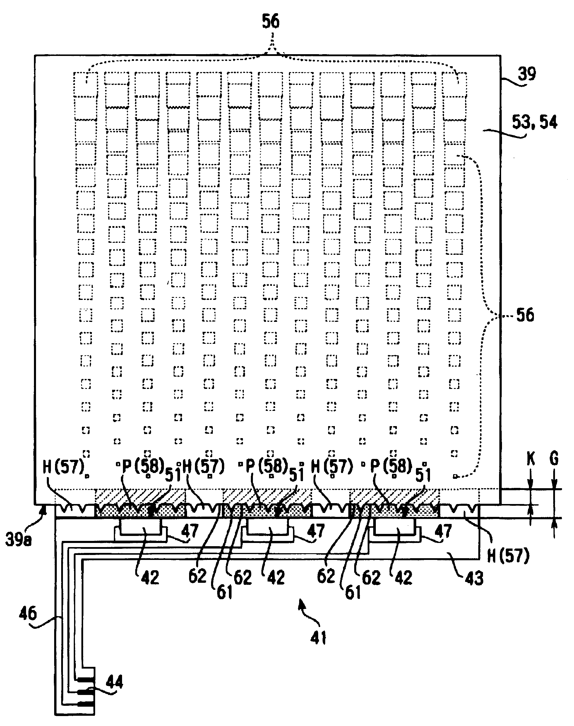
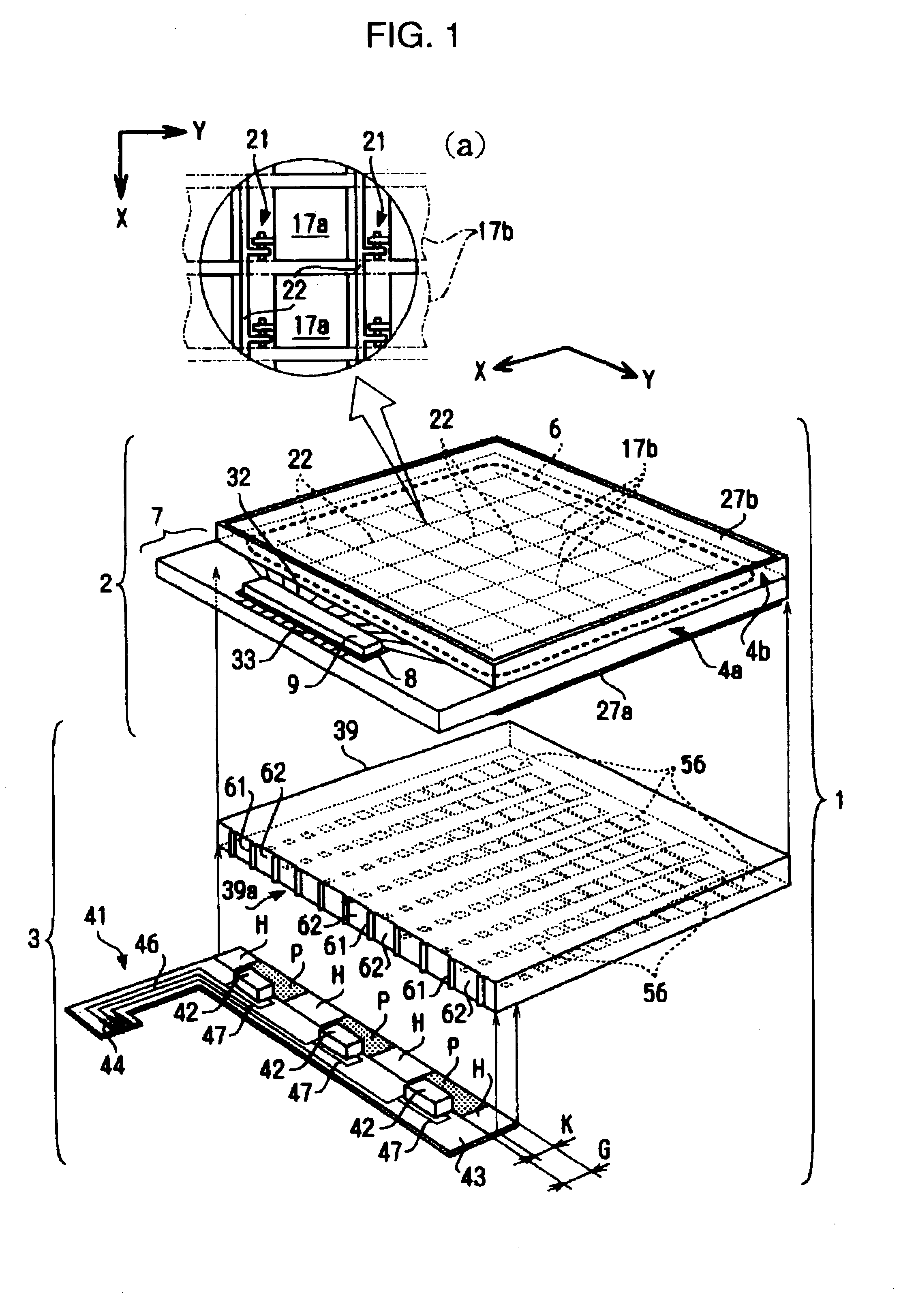
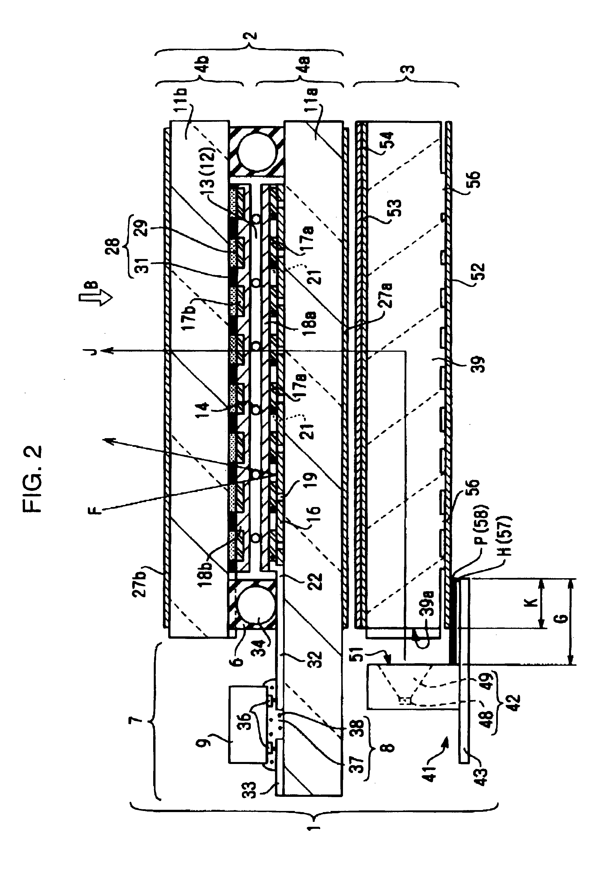
[0130]As shown in FIG. 13(a), the height of the prism face 61 was set at L1=10 to 50 μm, preferably 0.02 to 0.03 mm, the vertical angle to α=80 to 120°, the pitch to P1=100 to 300 μm, and the distance between the light-emitting face of the LED 42 and the light input face 39a of the light guide member 39 to D1=0.2 mm or less. Also, as shown in FIG. 13(b), the height of the light-emitting face of the LED 42 was set at H1=0.7 mm, the height of the LED 42 to H2=1.0 mm, and the height of the light input face 39a of the light guide member 39 to H3=0.8 to 0.9 mm. Setting the conditions for the LEDs 42 and prism faces 61 and so forth as described above, the locally-high-luminance areas were reduced to a level that poses no problems from a practical standpoint, and moreover, sufficient luminance of light emitted from the light guide member 39 was secured.

[0131]Second Embodiment

[0132]Next, in FIG. 14(a), for a light guide member 39, two inches in diagonal size, three typ...


PUM


Abstract

An illumination device is provided to solve locally high luminance near point-shaped light sources, while preventing overall decrease in luminance at the light-emitting face of a light guide member. The illumination device includes a light source for generating light, and a light guide member which receives light from the light source at a light input face and emits light from a light emitting face. A continuous optical pattern with prism faces and flat faces is provided on the light input face. Light emitted from the light source is diffused in the plane direction by the optical pattern, so there is no occurrence of locally-high-luminance areas near the LEDs in the light guide member. Moreover, the luminance of the light emitted in a planar manner from the light-emitting face does not decrease.

Description

BACKGROUND OF THE INVENTION[0001]1. Technical Field of the Invention[0002]The present invention relates to an illumination device for generating light, a liquid crystal device configured using the illumination device, and an electronic apparatus configured using the liquid crystal device.[0003]2. Description of the Related Art[0004]Currently, liquid crystal devices are widely used in cellular phones, portable information terminals, digital cameras, video camcorders, and other such electronic equipment. In many cases, the liquid crystal devices are used as display units for displaying images such as characters, numbers, shapes, and so forth.[0005]Generally, with liquid crystal devices, the orientation of liquid crystal molecules within the liquid crystal layer is controlled for each display dot by controlling the voltage applied to the liquid crystal for each display dot.[0006]The light passing through the liquid crystal layer is modulated by the orientation control of the liquid cry...

Claims


Application Information

Patent Timeline
IPC IPC(8): F21V8/00F21S2/00G02B6/00F21Y101/02G02F1/13357
CPCG02B6/0016G02B6/0061G02B6/0068G02B6/0036G02F1/1335
Inventor KAWAKAMI, HISANORI
Owner BOE TECH GRP CO LTD
Why Eureka
Try Eureka