Method of forming a composite bone material implant

a bone material and composite technology, applied in the field of bone composite implants, can solve the problems of difficult to achieve this goal, affecting the quality of bone tissue, and requiring the discarding of a great deal of scrap and powdered bone material,

Inactive Publication Date: 2006-02-21
MEREDITH THOMAS L
View PDF31 Cites 51 Cited by
  • Summary
  • Abstract
  • Description
  • Claims
  • Application Information

AI Technical Summary

Benefits of technology

[0022]It is known that allograft bone can be reshaped into one of many configurations for use as an implant. Various methods, including that of Bonutti, U.S. Pat. Nos. 5,662,710 and 5,545,222, can be used to shape allograft material into the desired shape.
[0023]A goal of a bone composite transplant is that the transplant is readily received and hosted by the receiving mammal, with bone fusion occuring (i.e., the composite should be biocompatible and osteoinductive). Today, the only other osteoinductive implants are allograft shapes that have been cut and shaped from cadaver donated bone. This method has serious drawbacks in that it is difficult for sufficient fusion to take place and the implant usually lacks sufficient structural strength and density.
[0024]U.S. Pat. No. 6,025,538 to Yaccarino, III, discloses allograft bone

Problems solved by technology

With respect to living bone tissue, it has been desirable in the past to be able to remove a piece of living tissue graft material which is the exact size and shape needed for the host site where it will be implanted, but it has often proved very difficult to achieve this goal.
A drawback of fabricating transplants and prostheses from donated allograft is that the process necessitates discard of a great deal of scrap and powdered bone material.
With a transplanted allograft, older bone may be too brittle and we

Method used


Image

  • Method of forming a composite bone material implant
  • Method of forming a composite bone material implant
  • Method of forming a composite bone material implant

Examples


example 1

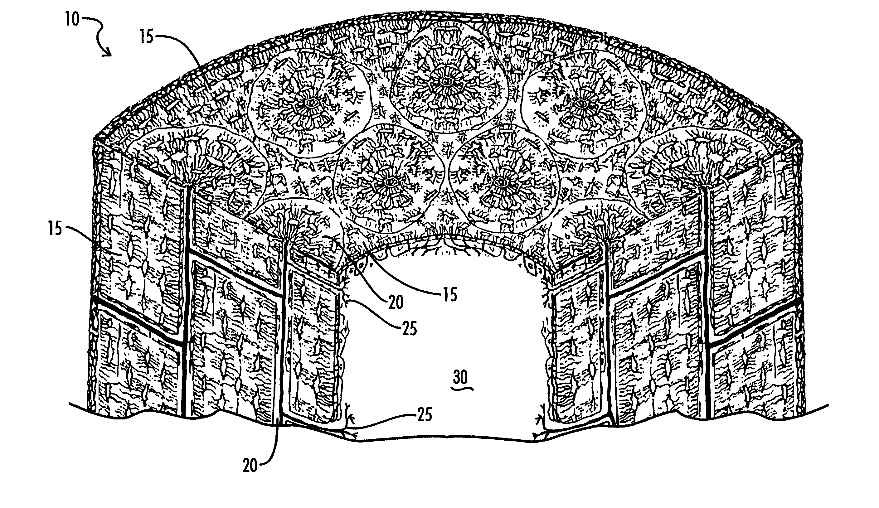
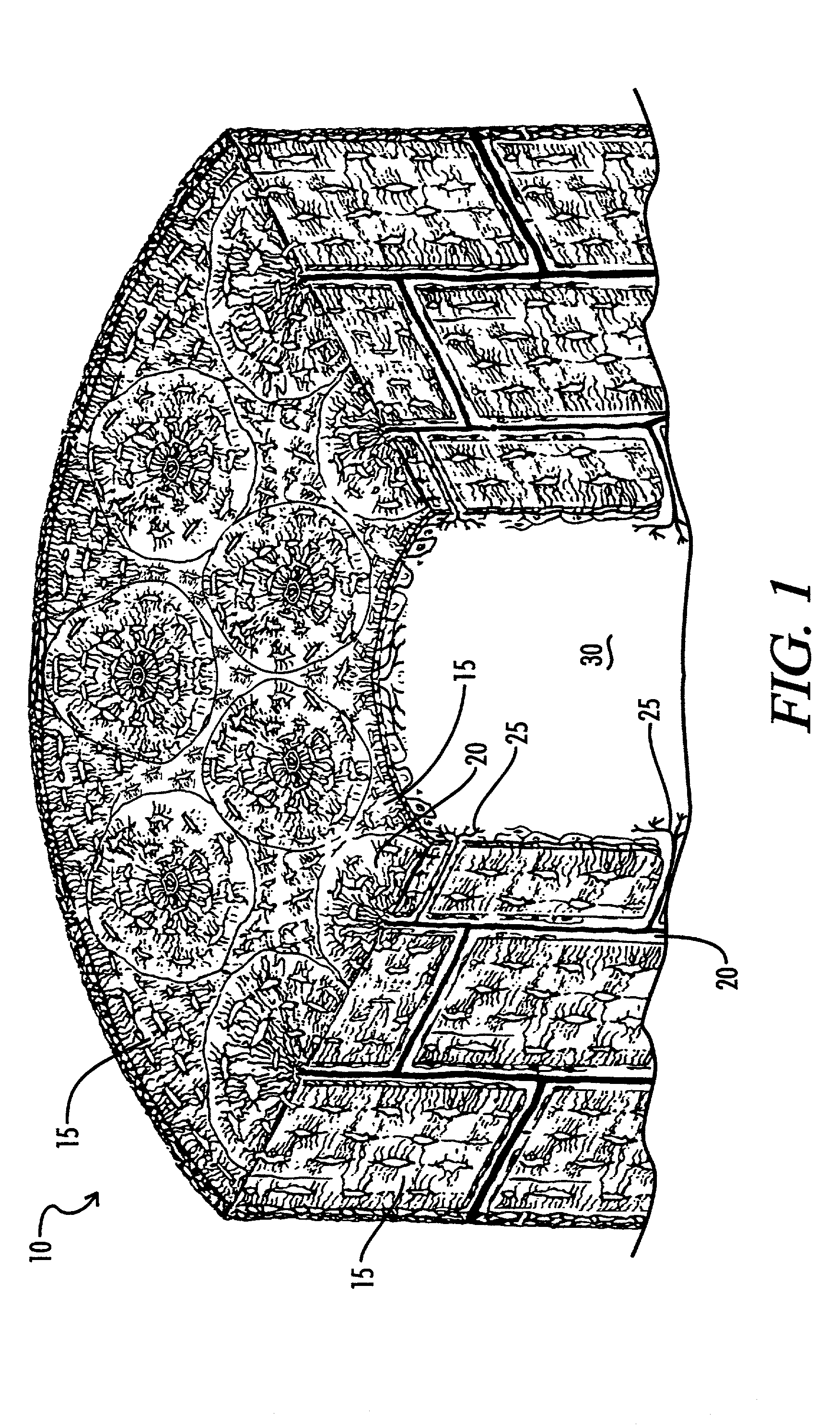
[0121]This example shows a process of making a tubular or cylindrical composite with a 2 cm OD (outside diameter) and 1.4 cm ID (inside diameter) by 2 cm in length, and 3 mm wall.

[0122]Cortical human bone is cleaned and ground into particles varying in size from 125 microns to 850 microns. The ground bone is demineralized, providing deminieralized bone matrix (DBM).

[0123]2.00 gms is measured, then hydrated with sterile water to a weight of 2.558 gms (0.558H2O). The weighed DBM is then inserted into the cylindrical cavity of a Teflon® mold and manually compacted with a force of 0.5 pounds. One (1) cc of special blended N Butyl Cyanoacrylate (CA) is then injected with a #18 gauge needle into the DBM at the outer edge of the cylindrical shape, and at the same time a vacuum of 28″ hg is applied from the bottom end of mold. Two (2) cc of same N Butyl Cyanoacrylate is then injected with a #18 gauge needle into the center core of the Teflon mold. The total weight of the bone composite is n...

example 2

[0125]Example 1 was repeated, to obtain the samples discussed below.

[0126]The densities of the samples were measured using physical density estimates and the water displacement method. Physical estimates measures a volume based upon physical measurement of the sample dimensions (height×width) and the dry weight of the sample. In this example, the samples were prepared by drying the sample in an oven at 110 C overnight. In the Water displacement method (ASTM D-792) the volume of water displaced is measured and the weight of the sample after drying is measured.

[0127]Density estimates based upon these two methods for five ART samples is presented in Table 1.

[0128]

TABLE 1Measured DensityWaterDisplacementdensity estimate,Physical Density Estimate,Sample IDgms / ccgms / ccHuman-1-A1.121.121.00Human-1-B0.960.980.86Rabbit-30.961.070.96Rabbit-41.091.070.83Rabbit-51.071.070.91Mean1.041.0620.9121.051

[0129]The weight loss on drying is presented in Table 2. The weight loss on drying is a combination...


PUM

PropertyMeasurementUnit
Lengthaaaaaaaaaa
Lengthaaaaaaaaaa
Fractionaaaaaaaaaa

Abstract

A method of forming a bone composite, comprising: providing bone tissue; grinding said bone tissue to form ground tissue; molding the ground bone tissue into a bone composite; applying a binder to the bone composite; applying a vacuum to the mold, and optionally milling or refining the bone composite to the desired shape. Additionally, bone tissue composites made therefrom are included. The composites may be, for example, a bone pin, screw, or prosthesis.

Description

[0001]This patent application is a continuation-in-part of U.S. patent application Ser. No. 09 / 615,643, filed Jul. 13, 2000 now abandoned, the contents of which are expressly incorporated herein by reference.FIELD OF THE INVENTION[0002]This invention generally relates to the field of bone composite implants and a method of forming bone composites. The bone composite implants, or osteoimplants, of the present invention may be used in the repair, replacement, and / or augmentation of various portions of animal or human skeletal systems. The bone composite implants of the present invention may be considered load-bearing implants.[0003]The composite of the present invention is generally formed from a process comprising grinding bone tissue to form ground tissue, molding the ground bone tissue at least under vacuum into a bone composite, and optionally applying a binder to the bone composite.BACKGROUND OF THE INVENTION[0004]The practice of donating and transplanting bone tissue is beginnin...

Claims


Application Information

Patent Timeline
IPC IPC(8): B29C43/56A61F2/28A61F2/30B29C43/02A61B17/68A61B17/80A61B17/86A61F2/00A61F2/46A61L27/36A61L27/48A61L31/00A61L31/12
CPCA61B17/866A61F2/28A61F2/4644A61L27/3608A61L27/365A61L27/3683A61L27/3691A61L27/48A61L31/005A61L31/129C08L35/04A61B17/68Y10S264/78A61B17/86A61F2002/2817A61F2002/30225A61F2002/30235A61F2002/30678A61F2002/30957A61F2002/4645A61F2230/0069A61L2430/02A61B17/80A61F2002/30677
Inventor MEREDITH, THOMAS L.
Owner MEREDITH THOMAS L
Why Eureka
Try Eureka