Electronic ballast for a discharge lamp

a technology of electronic ballast and discharge lamp, which is applied in the direction of instruments, light sources, process and machine control, etc., can solve the problems of affecting the effect of the discharge lamp

Active Publication Date: 2006-02-21
MATSUSHITA ELECTRIC WORKS LTD
View PDF10 Cites 28 Cited by
  • Summary
  • Abstract
  • Description
  • Claims
  • Application Information

AI Technical Summary

Benefits of technology

[0021]Still further, the discriminator may include a re-starting adjustor which gives a signal indicative of a downtime starting from the extinction of the lamp. The above predetermined value of the criterion set to decrease w

Problems solved by technology

Because of the mercury-free nature, xenon acts predominantly until a lamp temperature reaches to a certain level, thereby necessitating a relatively long rise time for the lamp to attain a sufficient luminous level.
Although it might be effective to give an increased lamp power at the start of the lamp for sho

Method used


Image

  • Electronic ballast for a discharge lamp
  • Electronic ballast for a discharge lamp
  • Electronic ballast for a discharge lamp

Examples


first embodiment

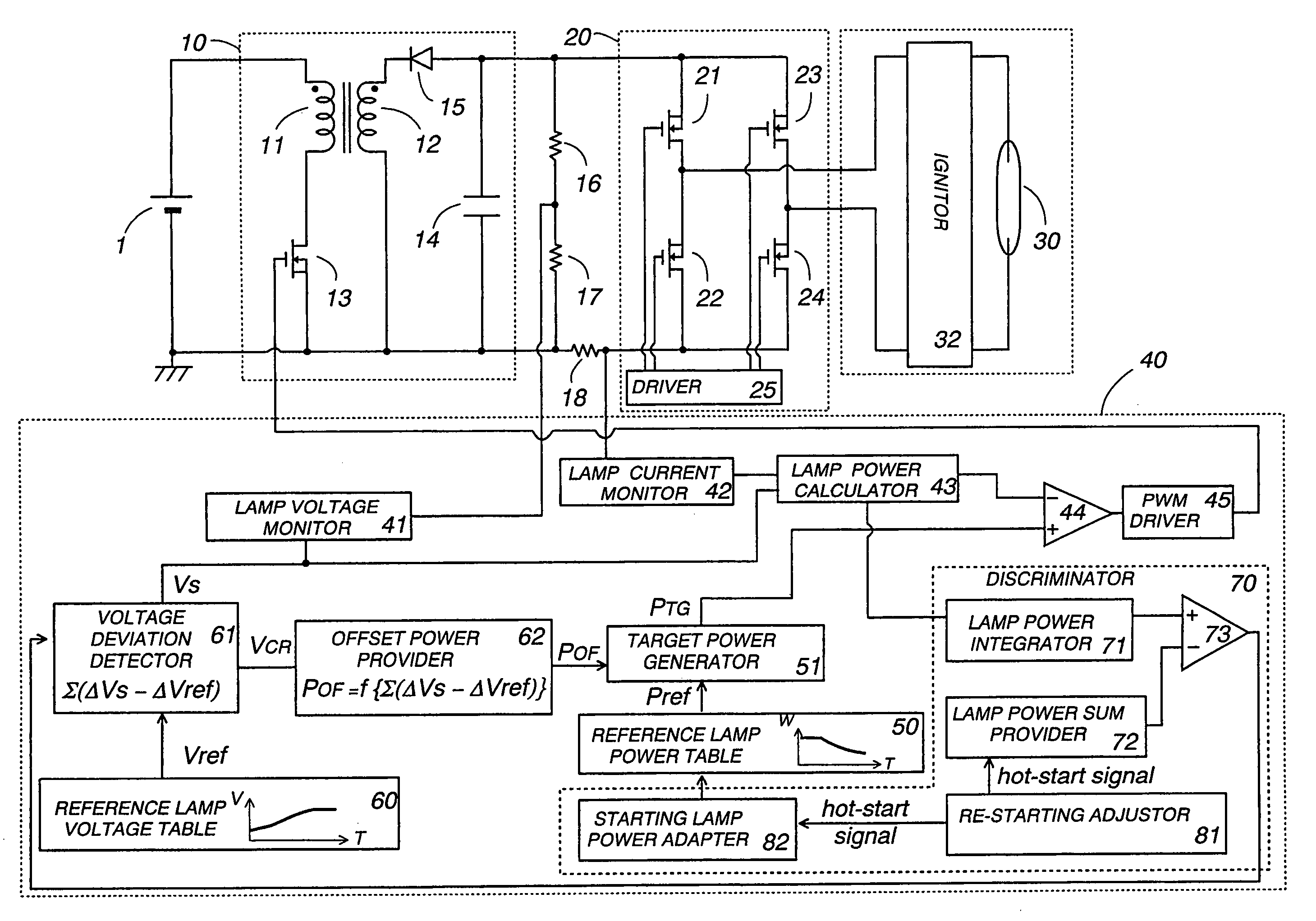
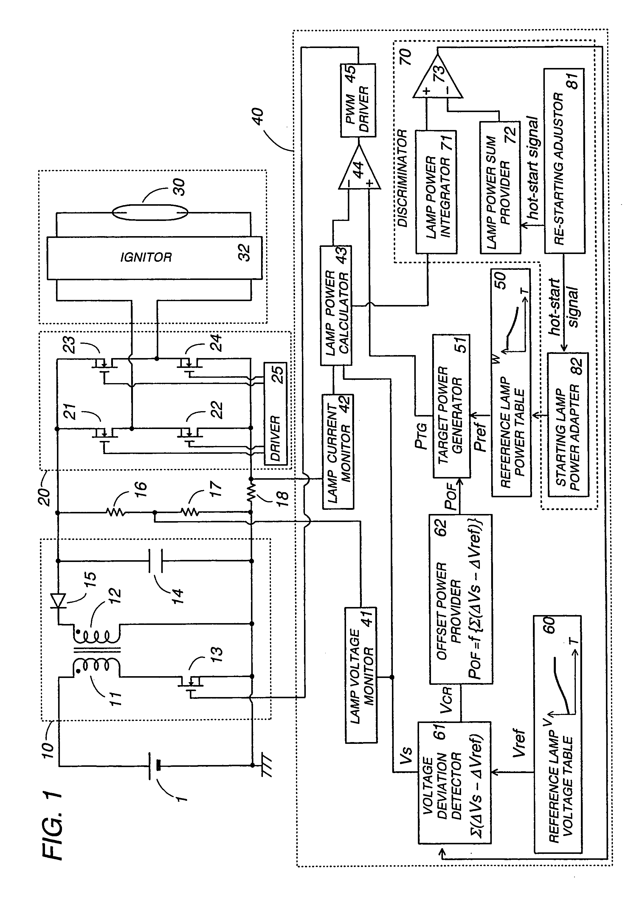
[0033]Referring now to FIG. 1, there is shown an electronic ballast for operating a gas discharge lamp in accordance with the present invention. The ballast includes a DC-DC converter 10 providing a regulated DC voltage from a fixed DC voltage source 1, an inverter 20 that receives the regulated DC voltage to give an AC power to a discharge lamp 30, and an ignitor 32 providing a high starting lamp voltage for starting the lamp 30. The converter 10 includes a transformer having a primary winding 11 and a secondary winding 12, and a switching transistor 13 which is connected in series with the primary winding 11 across the DC voltage source 1. A smoothing capacitor 14 is connected in series with a diode 15 across the secondary winding 12 to accumulate the DC voltage. The switching transistor 13 is driven to turn on and off at a varying duty ratio determined by a controller 40 in order to regulate the output DC voltage given to the inverter 20, and therefore a resulting AC power suppli...

second embodiment

[0053]FIG. 10 illustrates a modified ballast which is identical to the second embodiment except that the discriminator 70 decides time T1 by checking a gradient of the lamp voltage being monitored. Like parts are designated by like reference numerals. The discriminator 70 includes a voltage gradient calculator 78 which gives the lamp voltage gradient, and a target voltage gradient memory 79 storing a target gradient. When the instant lamp voltage gradient exceeds the target gradient, the comparator 77 issues the trigger signal for initiating the power correction and therefore defining time T1.

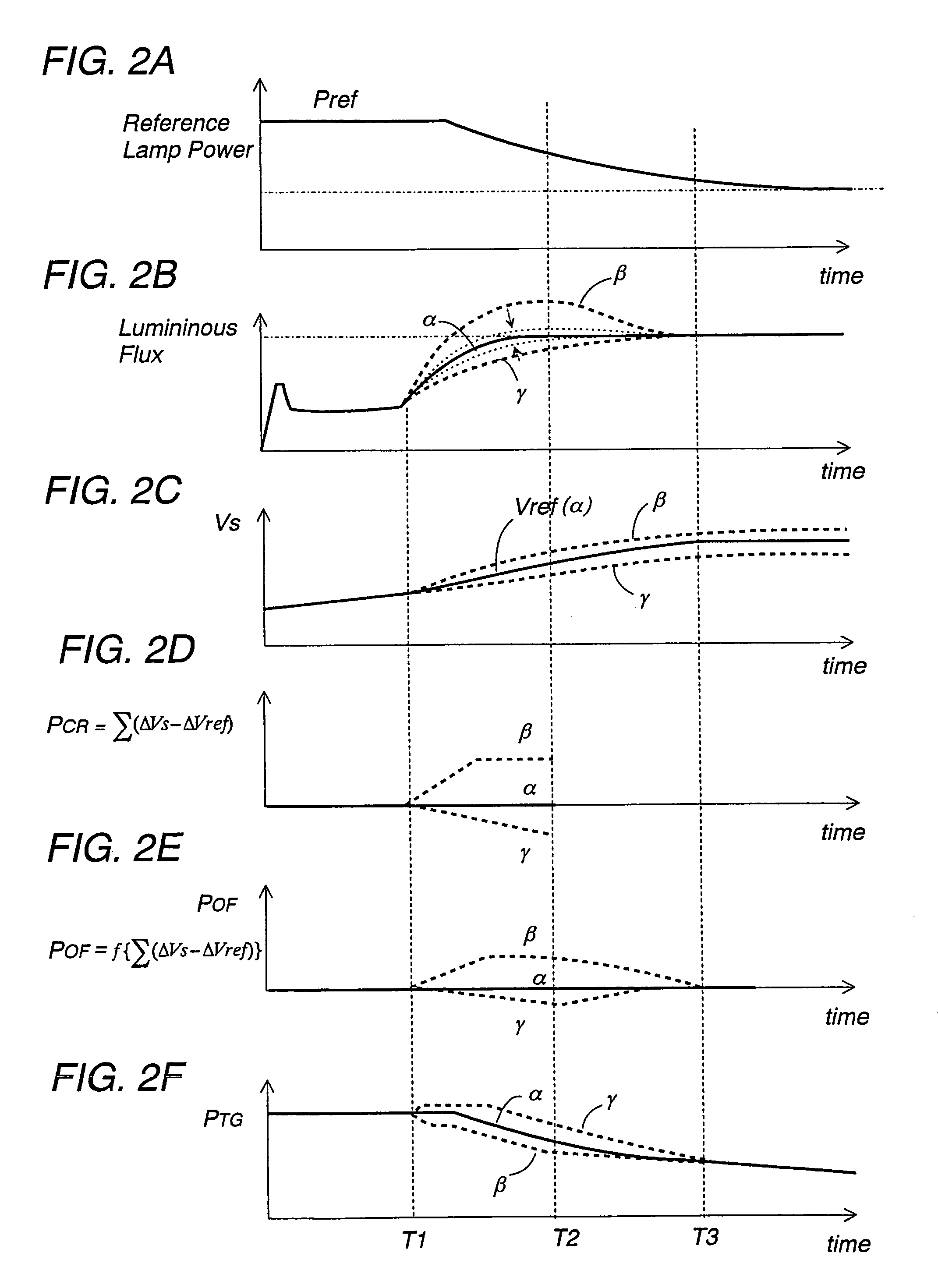
[0054]In the above embodiments and modifications, the discriminator 70 is illustrated in combination with the sophisticated power correction control as shown in FIGS. 2A to 2F. However, the specific schemes of determining the timing T1 disclosed herein could be utilized in combination with a simple scheme of reducing the lamp power after time T1, and accordingly could constitute a subject matte...


PUM


Abstract

An electronic ballast for a discharge lamp has a controller that increase luminous flux of the lamp to a stabilized level in a constant time irrespective of possible variations in lamp characteristic. The controller utilizes a reference lamp power table and a reference lamp voltage table respectively defining a reference lamp power and a reference voltage varying with time. The controller includes a voltage deviation detector that gives a voltage correction index indicating a voltage deviation between the reference voltage and a monitored lamp voltage. The voltage correction index is processed at an offset provider that gives an offset power. A target power generator is included to correct the reference lamp power in view of the offset power, thereby generating a target lamp power which is constantly updated and is supplied to the lamp.

Description

TECHNICAL FIELD[0001]The present invention relates to an electronic ballast for a discharge lamp, more particularly, a high intensity discharge lamp, for example, a metal halide lamp utilized as an automobile's head lamp and a projector lamp.BACKGROUND ART[0002]High intensity discharge lamps have been now utilized as automobile's head lamp and a projector lamp. Because of the nature of this application, the lamps have to increase luminous flux rapidly upon being turned on. Particularly, the automobile's lamps have to satisfy a requirement of increasing the luminous flux to a sufficiently high level within a few seconds. When designing the ballast that ensures a rapid increase of the luminous flux, it should be taken into consideration that a possible variation in lamp characteristic may bring about an appreciable delay in reaching a prescribed light output level due to overshooting or undershooting of the light output.[0003]Japanese Patent Publication No. 2946384 discloses a ballast...

Claims


Application Information

Patent Timeline
IPC IPC(8): G05F1/00H05B41/288H05B41/38
CPCH05B41/2882H05B41/388H05B41/386H05B41/382
Inventor KAMBARA, TAKASHITANAKA, TOSHIFUMI
Owner MATSUSHITA ELECTRIC WORKS LTD
Why Eureka
Try Eureka