Deposit detector and control device using it
a detector and control device technology, applied in the field of object sensors, can solve the problem that the conventional rain sensor cannot detect flashing phenomena
- Summary
- Abstract
- Description
- Claims
- Application Information
AI Technical Summary
Benefits of technology
Problems solved by technology
Method used
Image
Examples
embodiment 1
(Embodiment 1)
[0063]First of all, the first object sensor of the present invention will be explained.
[0064]The first object sensor of the present invention has a function of estimating not only the presence or absence of an object on a sensing surface of a transparent substrate but also a surface shape of the object and a flashing phenomenon that occurs due to a surface shape effect through the detection of the increasing rate of the quantity of incident light that is incident from extraneous light. In the Embodiments mentioned below, in particular, the case where a raindrop is deposited on a sensing surface will be explained as an example.
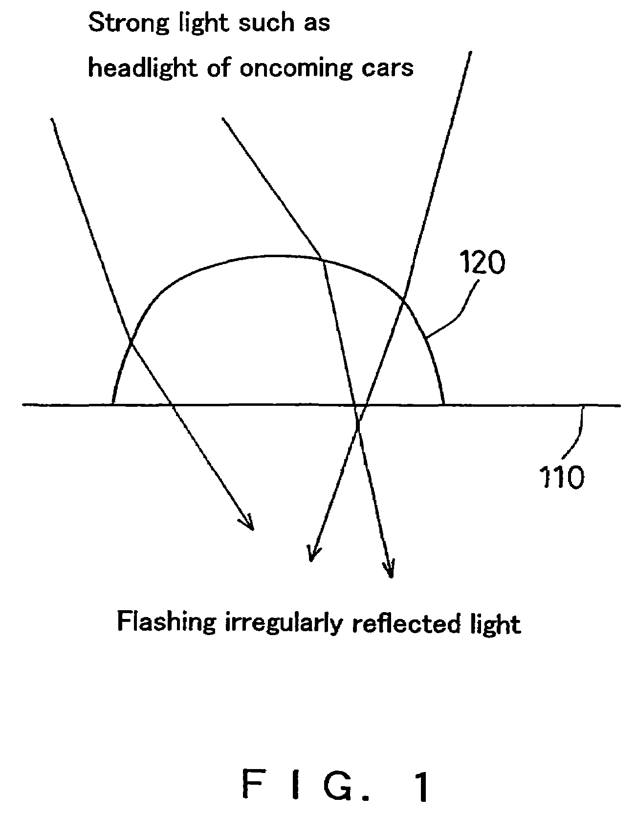
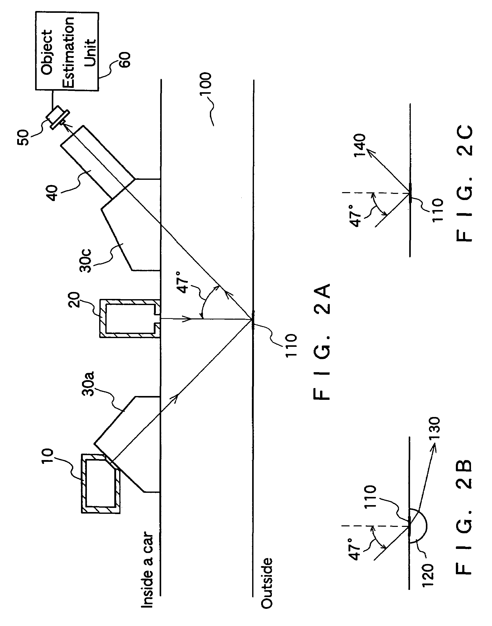
[0065]First of all, the principle in which a flashing phenomenon occurs due to the surface shape effect of an object will be explained briefly. Next, an apparatus configuration of an object sensor of the present invention, an operation and estimation processing in an object sensing mode, an operation and estimation processing in a light-scattering...
embodiment 2
(Embodiment 2)
[0133]Embodiment 2 shows another embodiment of the first object sensor of the present invention. Embodiment 2 simply shows the object sensor shown in Embodiment 1 and the object sensor in Embodiment 2 has a configuration in which the light-scattering object sensing unit is simplified. The object sensor has a function of estimating a flashing phenomenon due to a raindrop through the detection of the presence of a raindrop on the sensing surface by the object sensing unit and the detection of the increase rate of the quantity of incident light incident from the extraneous light by the extraneous light quantity increase detection unit.
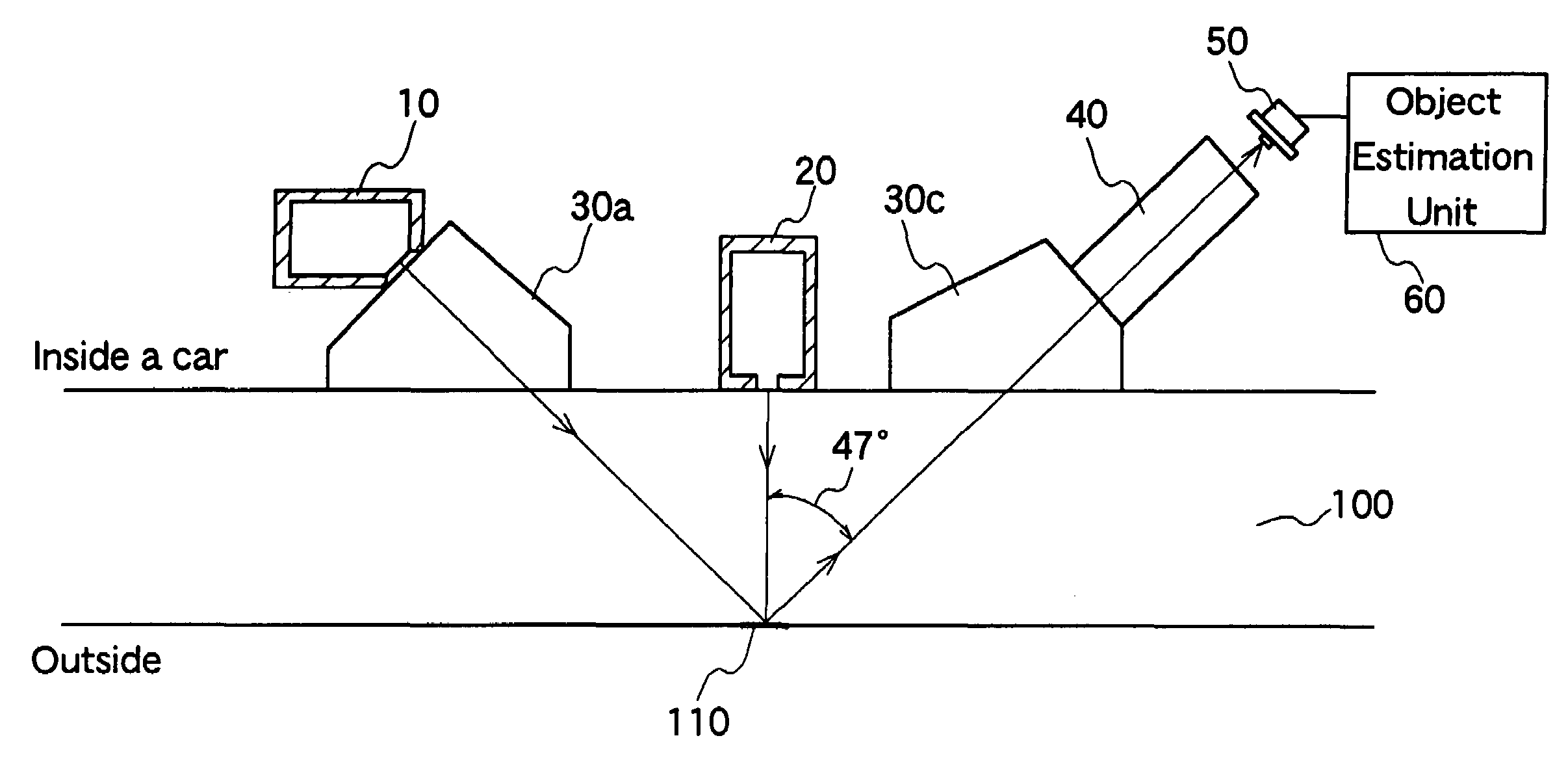
[0134]FIG. 10 is a schematic view simply showing an example of an apparatus configuration of the object sensor of Embodiment 2. In FIG. 10, reference numeral 100 denotes a windshield; 110 denotes a sensing surface; 10 denotes a light source for total reflection; 30a and 30c denote a prism, respectively; 40 denotes a converging lens; 50 denot...
embodiment 3
(Embodiment 3)
[0138]Embodiment 3 shows an embodiment of a second object sensor of the present invention. In the second object sensor according to Embodiment 3 of the present invention, a sensing surface is an outer surface of a transparent substrate; the light-receiving element array having a plurality of micro light-receiving elements receives the sensing surface emitted with extraneous light by an image formation-system lens; the light-receiving element array produces a signal pattern in which light detection signals from micro light-receiving elements of the light-receiving element array are arranged in accordance with the micro light-receiving elements and outputs the signal pattern corresponding to the state in which an object is deposited on the sensing surface. By analyzing the change in the signal pattern, the presence or absence of an object on the sensing surface, the kinds of the object and the occurrence of a flashing phenomenon, etc. are detected.
[0139]In the second obj...
PUM
| Property | Measurement | Unit |
|---|---|---|
| refractive index | aaaaa | aaaaa |
| refractive index | aaaaa | aaaaa |
| refractive index n2 | aaaaa | aaaaa |
Abstract
Description
Claims
Application Information
 - R&D
- Intellectual Property
- Life Sciences
- Materials
- Tech Scout
- Unparalleled Data Quality
- Higher Quality Content
- 60% Fewer Hallucinations
Browse by: Latest US Patents, China's latest patents, Technical Efficacy Thesaurus, Application Domain, Technology Topic, Popular Technical Reports.
© 2025 PatSnap. All rights reserved.Legal|Privacy policy|Modern Slavery Act Transparency Statement|Sitemap|About US| Contact US: help@patsnap.com


