PLL cycle slip detection

a phase detector and cycle technology, applied in the field of frequency synthesis, can solve the problem that the phase detector used in the pll circuit cannot provide linear detection

Inactive Publication Date: 2006-02-21
ERICSSON INC
View PDF8 Cites 63 Cited by
  • Summary
  • Abstract
  • Description
  • Claims
  • Application Information

AI Technical Summary

Benefits of technology

[0007]Each cycle slip detector includes slip detection logic for a corresponding input flip-flop in the PFD. The slip detection logic is configured to assert a cycle slip indicator signal based on receiving a clock edge in its corresponding input signal while the reset signal is asserted, or before the PFD has been properly reset. A logic circuit detects whenever a corresponding input flip-flop in the PFD has its output control signal asserted, or when the reset signal is asserted. This detection function operates to provide an output flip-flop with a high data signal if either condition exists. This output flip-flop is clocked by the same input signal that clocks the corresponding input flip-flop in the PFD. Thus, if the output flip-flop receives a clock edge in the corresponding input signal during either condition, it generates a cycle slip indicator signal. Once its data input signal is de-asserted, a subsequent clock edge in the corresponding input signal causes the output flip-flop to clear its cycle slip indicator signal.

Problems solved by technology

Generally, phase detectors used within PLL circuits cannot provide linear detection when the phase difference between two signals is greater than ±2π radians.

Method used


Image

  • PLL cycle slip detection
  • PLL cycle slip detection
  • PLL cycle slip detection

Examples


Embodiment Construction

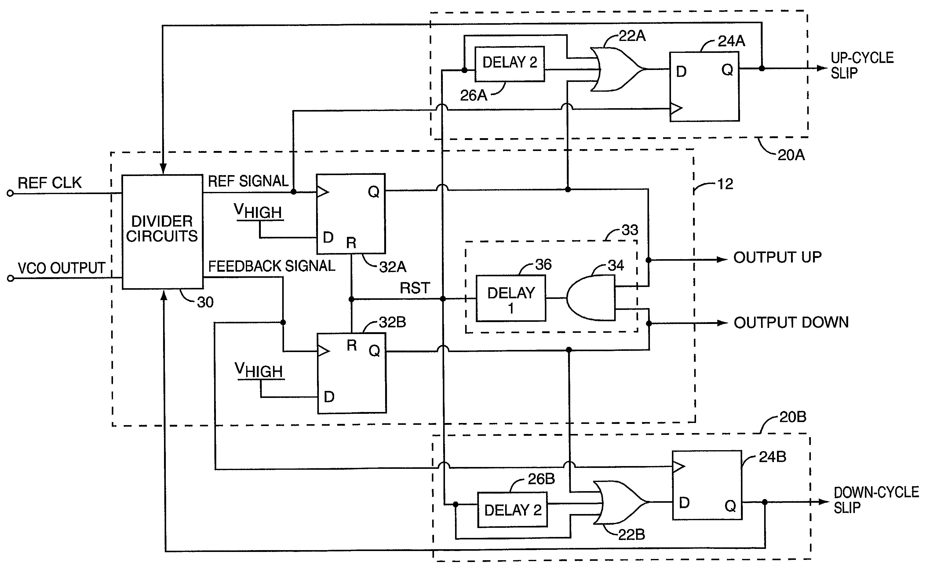
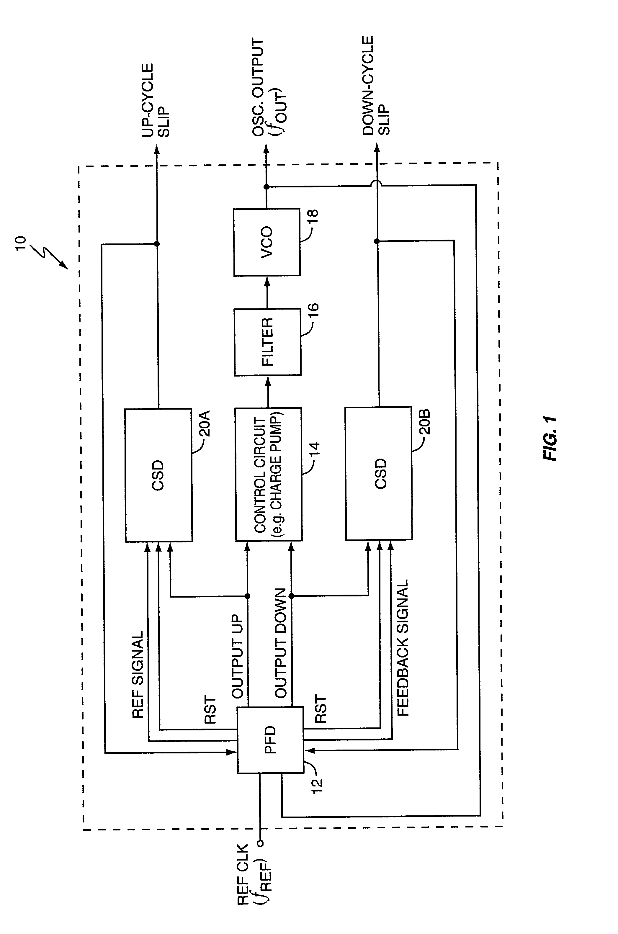
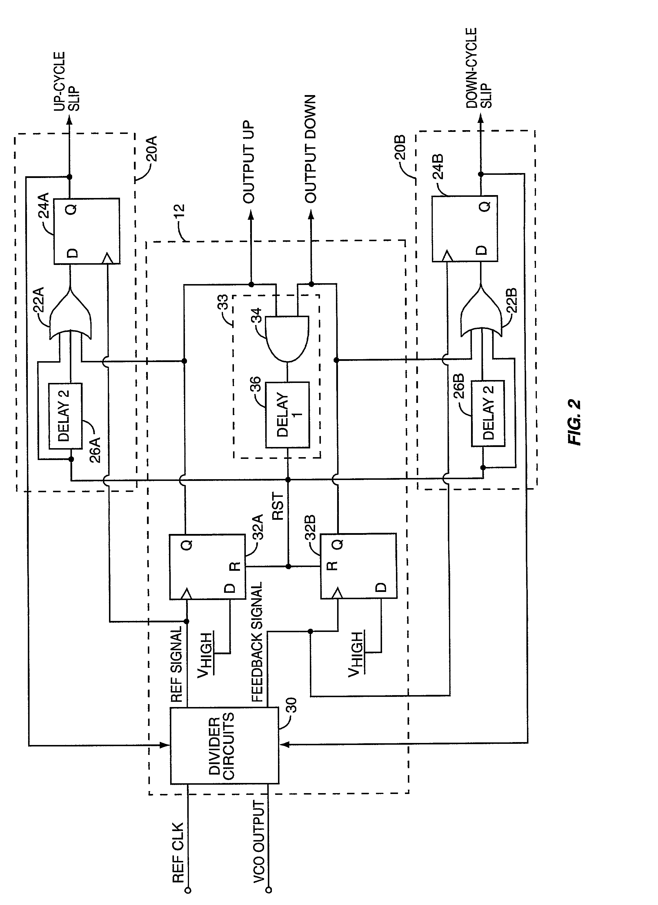
[0013]Turning now to the drawings, FIG. 1 is a diagram of a phase-locked loop (PLL), generally referred to by the numeral 10. The PLL 10 comprises a phase / frequency detector (PFD) 12, a control circuit 14, a loop filter 16, a voltage-controlled oscillator (VCO) 18, and cycle slip detectors 20.

[0014]In general, the PFD 12 generates PLL control signals based on the phase difference between two input signals. As shown, the PFD 12 receives two input signals, one based on the output from a reference clock (typically a crystal oscillator), and one based on the output signal from the VCO 18. The PLL 10 operates to make the VCO output signal have a frequency that is a desired multiple or fraction of the reference clock's output signal. The PFD 12 generates the PLL control signals as an OUTPUT UP and an OUTPUT DOWN signal for the control circuit 14. The OUTPUT UP and OUTPUT DOWN signals cause the control circuit 14 to adjust the control voltage applied to the VCO 18. The control circuit 14 m...


PUM


Abstract

A cycle slip detector interfaces with a phase/frequency detector (PFD), such as might be used in a phase-locked loop circuit (PLL), and indicates when cycle slips occur in the PFD. Typically, the PFD generates output control signals as a function of the phase difference between first and second input signals, with the first input signal usually serving as a reference signal against which the PLL adjusts the second input signal. The PFD provides linear phase comparison between its input signals, provided their relative phase difference does not exceed ±2π radians. If one of the two signals leads or lags the other by more than that amount, a cycle slip occurs, and the PFD responds nonlinearly. The cycle slip detector provides logic for detecting and indicating leading and lagging cycle slips as they occur in the PDF, and is typically implemented as a minimal arrangement of logic gates and flip-flops.

Description

BACKGROUND OF THE INVENTION[0001]The present invention generally relates to frequency synthesis, and particularly relates to PLL-based frequency synthesis.[0002]Radio frequency (RF) communications equipment, such as mobile terminals within a wireless communication system, use precise timing or frequency reference signals to receive and transmit signals. Often, such a reference signal is used to derive additional signals, possibly of higher or lower frequency, but with the stability and accuracy inherent in the reference signal. This frequent need to slave the frequency or timing of one signal to another, or to monitor the phase or frequency difference between two signals, gives rise to specialized circuits, such as the phase-locked loop (PLL).[0003]A general PLL configuration has a controllable oscillator generating an output signal, a detector generating an error signal based on the phase or frequency difference between a feedback signal derived from the output signal and an input ...

Claims


Application Information

Patent Timeline
Patent Type & Authority Patents(United States)
IPC IPC(8): H03D3/24H03L7/089H03L7/199
CPCH03L7/199H03L7/0891
Inventor HOMOL, DAVIDJONES, THERONKLEMMER, NIKOLAUS
Owner ERICSSON INC
Why Eureka
Try Eureka