
Fuel injection system for outboard motor

a technology of fuel injection and outboard motor, which is applied in the direction of fuel injection pumps, liquid fuel feeders, machines/engines, etc., can solve the problems of reducing the accuracy of fuel pressure measurement, inaccurate amount of fuel being injected into the combustion chamber, and calculating fuel pressure, so as to reduce the pressure pulsation

Inactive Publication Date: 2006-02-28
YAMAHA MARINE KK
View PDF13 Cites 22 Cited by
  • Summary
  • Abstract
  • Description
  • Claims
  • Application Information

AI Technical Summary

Benefits of technology

[0010]One aspect of the present invention is the recognition that the bottom of a fuel rail reflects pressure pulsations. It is further recognized that inserting a pulsation damper at the end of the fuel rail significantly reduces the pressure pulsation at the fuel injectors. This is especially true for the fuel injectors located near the end of the fuel rail because they typically experience the greatest amount of fuel pulsation.
[0014]In accordance with another aspect of the invention, a direct fuel injected system for an internal combustion engine includes a high pressure fuel pump for developing high pressure fuel and a fuel injector to directly injector fuel into a combustion chamber of the engine. The system also including a fuel pressure sensor that communicates with said fuel system for measuring a fuel pressure within the fuel system. The system also including means for reducing fuel pressure fluctuations within the fuel system.

Problems solved by technology

There are several problems associated with calculating the fuel pressure.
This reduces the accuracy of the fuel pressure measurement, which can result in an inaccurate amount of fuel being injected into the combustion chamber.
This can impair the emissions, fuel economy and power of the engine.
Another problem associated with calculating fuel pressure is that the fuel pressure sensors themselves often produce inaccurate measurements.
Fuel pressure sensors typically include fine distortion gauges and circuits that are easily damaged, especially by excessive vibration.
Accordingly, it is difficult to prevent the fuel pressure sensor from being damaged by the engine vibrations.
This can also result in an inaccurate amount of fuel being injected into the combustion chamber.

Method used


Image

  • Fuel injection system for outboard motor
  • Fuel injection system for outboard motor
  • Fuel injection system for outboard motor

Examples


Embodiment Construction

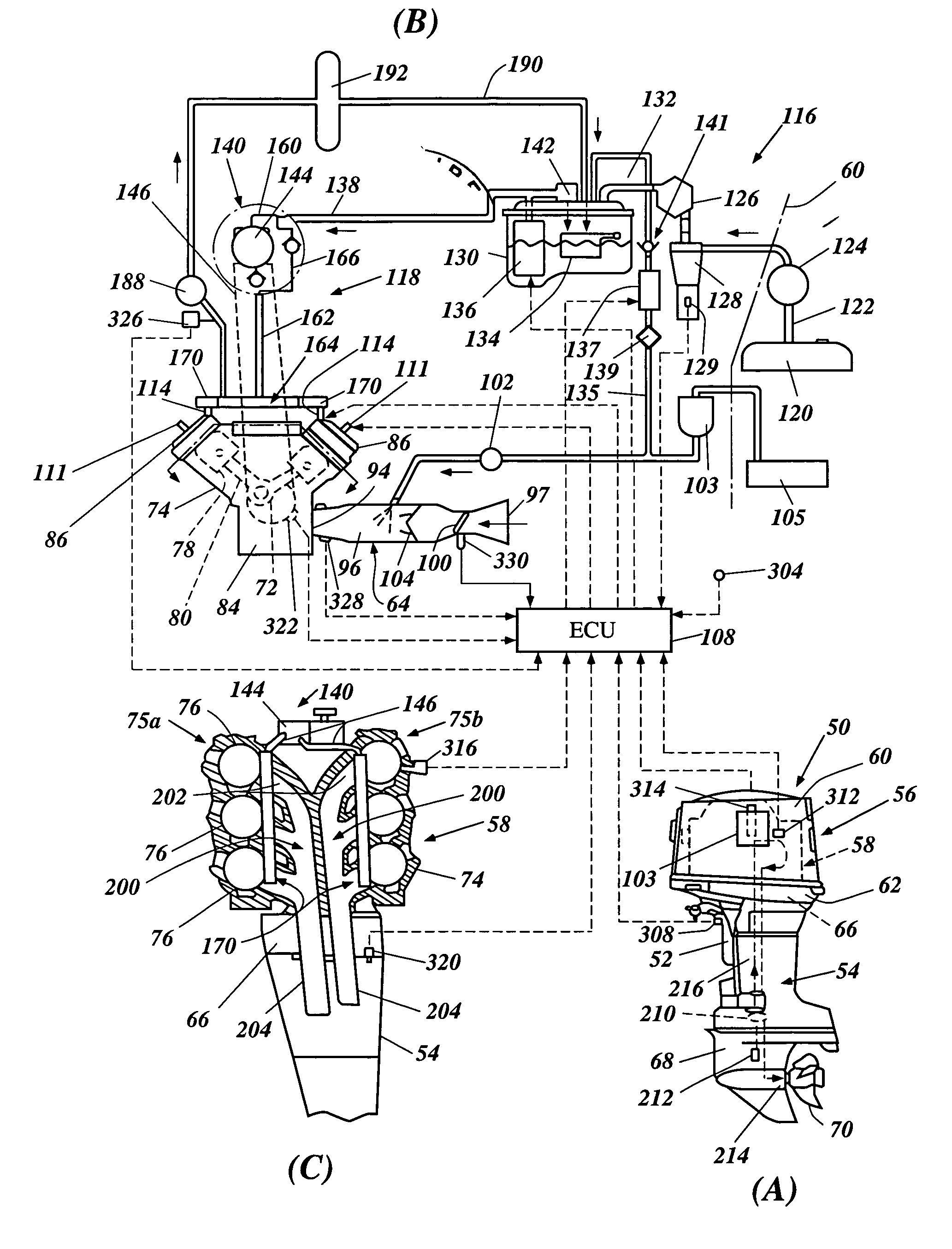
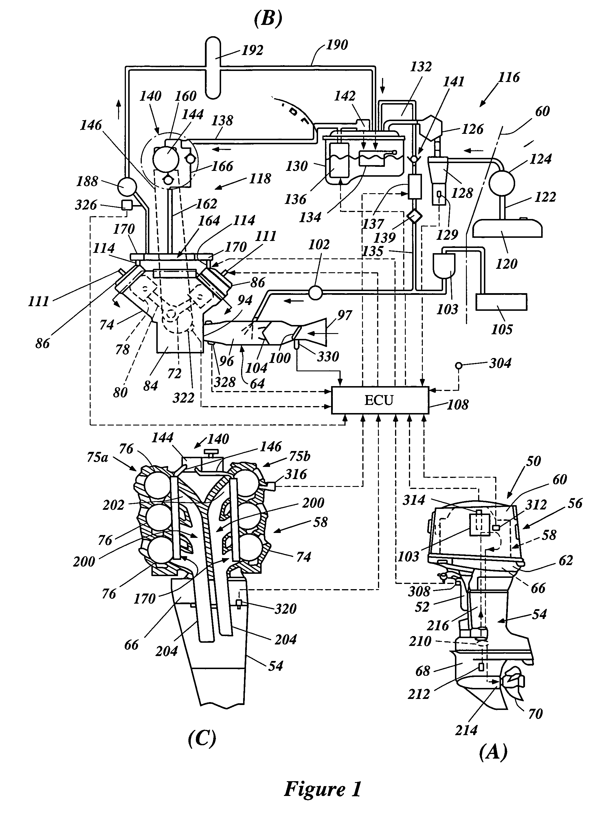
[0031]With reference now to FIG. 1, an outboard motor with a fuel supply system having certain features, aspects and advantages of the present invention will be described. While the present invention will be described in the context of the outboard motor, it is anticipated that the present fuel supply system can have utility in other environments of use. For instance, the fuel supply system can be used in any vehicular application featuring a fuel supply system, such as automotive and marine applications. Moreover, the present fuel supply system can also be used in stationary engines, such as those found on generators, for instance.

[0032]In the lower right hand view of FIG. 1 (i.e., FIG. 1(A)), the outboard motor is depicted in side elevation view and is identified generally by the reference numeral 50. The outboard motor 50 preferably includes a clamping arrangement 52. The clamping arrangement 52 is used to attach the outboard motor 50 to the hull of the watercraft (not shown) in ...


PUM


Abstract

An engine of an outboard motor includes a fuel injection system that is configured to increase the accuracy of fuel pressure measurements and more precisely control the amount of fuel injected. In a preferred mode, the fuel injection system can include a pressure dampening device that is connected to the direct fuel injected system. The system can also include a vibration dampening apparatus that protects a pressure sensor from damage that can be caused by engine vibrations.

Description

PRIORITY INFORMATION[0001]The present application is based on and claims priority to Japanese Patent Application No. 11-236461, filed Aug. 24, 1999, and Japanese Patent Application No. 11-236462, filed Aug. 24, 1999. The entire contents of these applications are hereby expressly incorporated by reference.BACKGROUND OF THE INVENTION[0002]1. Field of the Invention[0003]This invention relates to a fuel supply system for a direct fuel injected engine. More particularly, the present invention relates to an improved fuel supply system that is most suitable for direct fuel injected engines used outboard motors.[0004]2. Related Art[0005]In all fields of engine design, there is a demand for obtaining more effective emission control and better fuel economy while at the same time increasing power output. To meet this demand, fuel injection systems have replaced carburetors as the engine charge former. In such systems, fuel is typically injected into an intake air manifold. In order to achieve ...

Claims


Application Information

Patent Timeline
IPC IPC(8): F02M37/04
CPCF02M55/025F02M61/166F02M55/04F02F7/0068F02F7/008F02M2200/40F02M2200/24F02M2200/315
Inventor KATO, MASAHIKO
Owner YAMAHA MARINE KK
Learn More