Thermal decomposer for waste
- Summary
- Abstract
- Description
- Claims
- Application Information
AI Technical Summary
Benefits of technology
Problems solved by technology
Method used
Image

Examples
first embodiment
(First Embodiment)
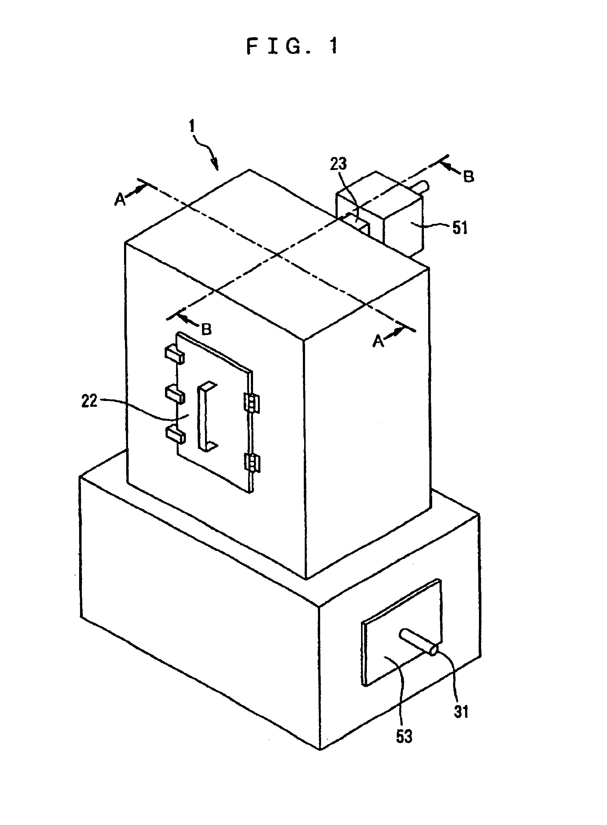
[0075]The apparatus 1 includes an internal heating chamber 10 with an inlet port 20 on its front (on the left side thereof in FIG. 3) through which the wastes are introduced into the heating chamber 10 and an outlet port 21 on its rear (on the right side thereof in FIG. 3) through which the resulting thermally decomposed wastes are discharged from the heating chamber 10. The inlet port 20 has an operable door 22 such that when closed provides an airtight seal of the heating chamber 10.
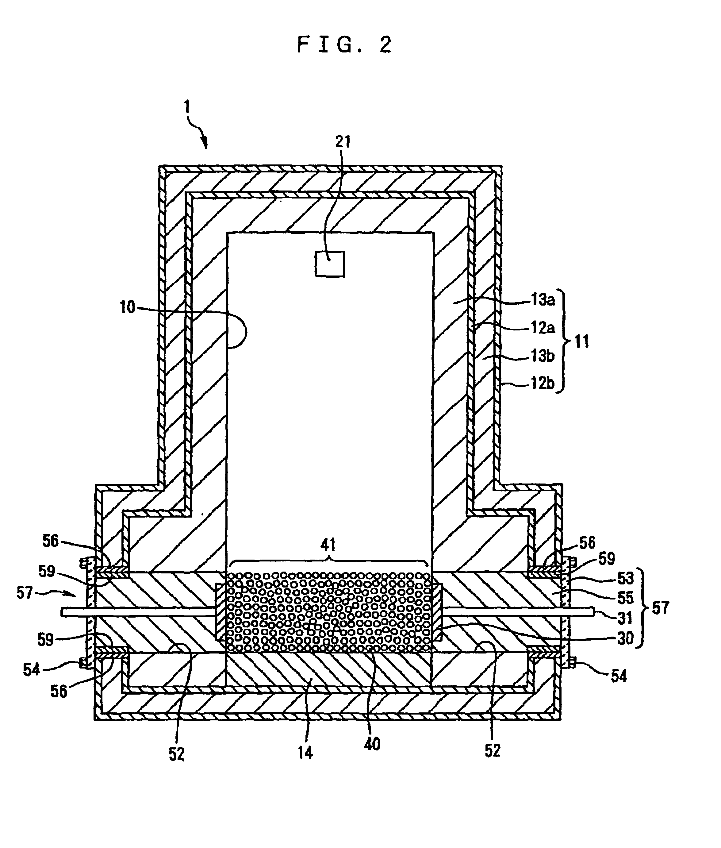
[0076]The thermal decomposition apparatus 1 has an outer wall 11 of a 4-layered structure composed of an innermost refractory concrete layer 13a, an inner iron plate 12a, an outer refractory concrete layer 13b, and an outermost iron plate 12b coated with a heat resistant coating. A portion of the innermost refractory concrete layer 13a positioned under a plurality of balls 40 in the form of spheres is replaced with a heat-resistant firebrick layer 14 whose joints are filled with a mon...
second embodiment
(Second Embodiment)
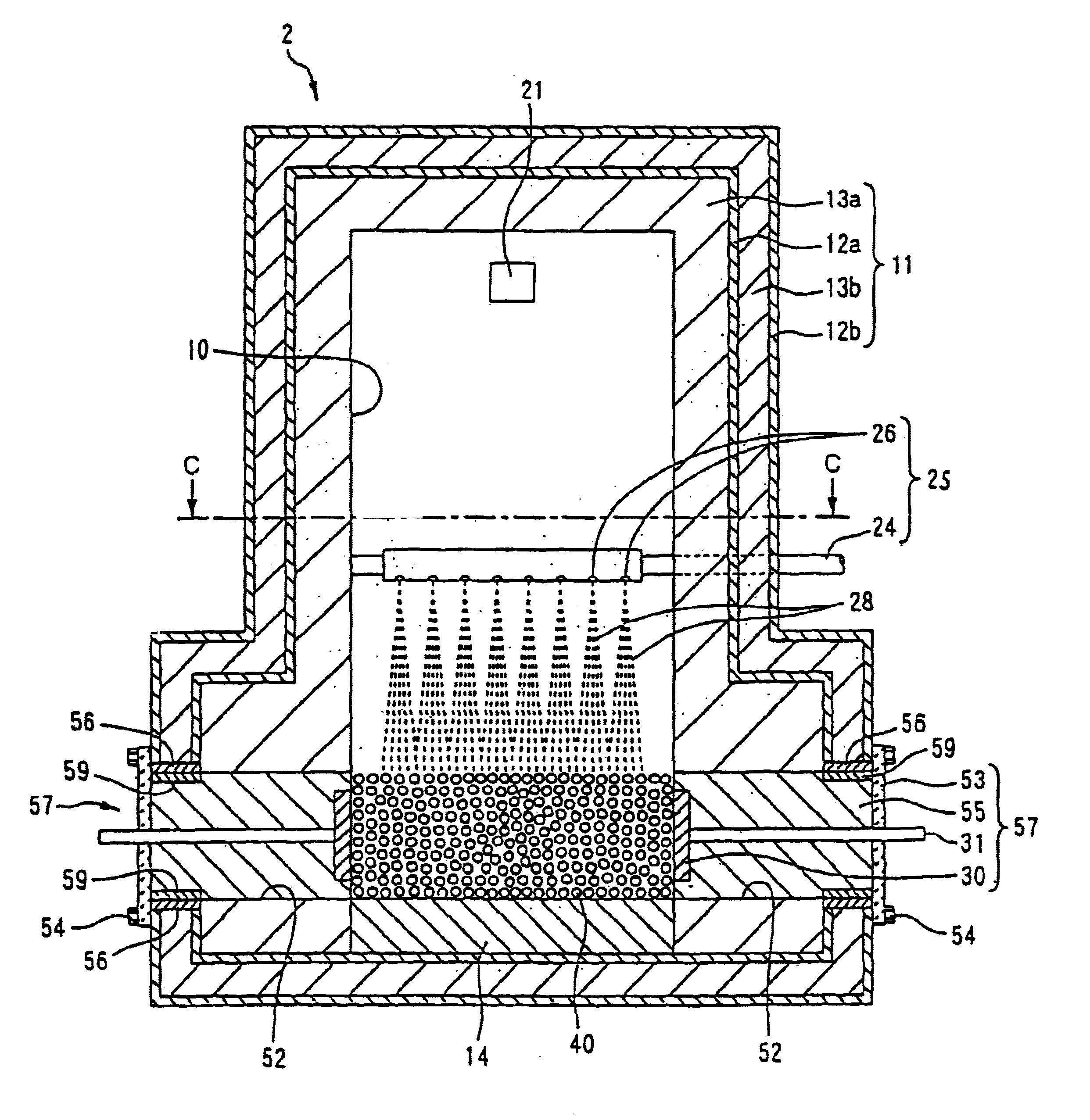
[0111]FIG. 7 is a vertical cross-sectional view of a thermal decomposition apparatus 2 for wastes in the second embodiment. FIG. 8 is a horizontal cross-sectional view taken along a line C—C in FIG. 7. The same reference numeral is used to denote the identical or similar elements of the second and first embodiments in FIGS. 7, 8 and 1-4.
[0112]The thermal decomposition apparatus 2 of the second embodiment has an inlet port 25 suitable for introducing liquid wastes such as waste oils, waste liquids and / or PCBs into the heating chamber, and is suitable for disposition of such liquid-like wastes. Further description of elements of the thermal decomposition apparatus 2 of the second embodiment identical or similar to those of the thermal decomposition apparatus 1 of the first embodiment will be omitted and only elements of the second embodiment different from those of the first embodiment will be explained next.
[0113]An inlet pipe 24 extends into the heating chamber 10...
third embodiment
(Third Embodiment)
[0118]FIG. 9 is a perspective view of a thermal decomposition apparatus 3 for wastes as a third embodiment. FIG. 10 is a horizontal cross-sectional view of a decomposed gas harm eliminating device 3b of the thermal decomposition apparatus 3.
[0119]The thermal decomposition apparatus 3 as the third embodiment comprises a thermally decomposing device 3a and a decomposed gas harm eliminating device 3b connected to the thermal decomposing device 3a. The thermal decomposing device 3a thermally decomposes the wastes. The decomposed gas harm eliminating device 3b heats to a high temperature gases produced by thermal decomposition of the wastes in the thermal decomposing device 3a to thermally decompose harmful substances remaining in the decomposed gases, thereby rendering the decomposed gases harmless.
[0120]The thermally decomposing device 3a is identical to the thermal decomposition apparatus 1 of the first embodiment except that the former lacks a filter such as that sh...
PUM
| Property | Measurement | Unit |
|---|---|---|
| Temperature | aaaaa | aaaaa |
| Percent by mass | aaaaa | aaaaa |
| Pressure | aaaaa | aaaaa |
Abstract
Description
Claims
Application Information
 - R&D
- Intellectual Property
- Life Sciences
- Materials
- Tech Scout
- Unparalleled Data Quality
- Higher Quality Content
- 60% Fewer Hallucinations
Browse by: Latest US Patents, China's latest patents, Technical Efficacy Thesaurus, Application Domain, Technology Topic, Popular Technical Reports.
© 2025 PatSnap. All rights reserved.Legal|Privacy policy|Modern Slavery Act Transparency Statement|Sitemap|About US| Contact US: help@patsnap.com