Device for measuring blood coagulation and method thereof

a technology for measuring devices and blood coagulation, which is applied in the direction of instruments, catheters, diagnostic recording/measuring, etc., can solve the problems of life-threatening clinical conditions, unwanted clotting, and persistent clots, and achieves the effect of simple and inexpensiv

Inactive Publication Date: 2006-02-28
LIFESCAN IP HLDG LLC
View PDF5 Cites 357 Cited by
  • Summary
  • Abstract
  • Description
  • Claims
  • Application Information

AI Technical Summary

Benefits of technology

[0028]It is an object of the invention to provide a simple and inexpensive apparatus and method which is capable of measuring clotting times on a whole blood or plasma sample (herein defined as sample fluid).

Problems solved by technology

Whilst formation of the clot is essential, the persistence of such clots would be dangerous to the body.
However, thrombosis is one of the leading causes of death worldwide due to the flow of blood to vital organs and tissues being blocked by blood clots.
Thrombosis may occur anywhere within the circulatory system, however it can be especially life threatening when this occurs in the lower body, heart, lungs or brain resulting in deep vein thrombosis, acute myocardial infarction, pulmonary embolism and acute isechemic stroke.
People who suffer from cardiac or vascular diseases and patients that have undergone surgical procedures are at risk of developing blood clots that may result in life-threatening clinical conditions.
However, the amount of anticoagulant in the bloodstream must be maintained at the proper level; too little may result in unwanted clotting whilst too much can result in haemorrhaging.
However, the traditional expression of PT test results is inadequate for international comparison because the values depend upon the nature of the thromboplastin used.
Formation of complexes on the surface of the phospholipid enables prothrombin to be converted into thrombin, which results in clot formation.
Monotoring is important and underdosing or overdosing of heparin may result respectively in pathological thrombus formation or serious hemorrhagic conditions.
Furthermore platelet dysfunction is one o the several major causes of bleeding after cardiopulmonary bypass.
However movement in the wires causes variability in the interelectrode dictance and in the impedance measurements.

Method used


Image

  • Device for measuring blood coagulation and method thereof
  • Device for measuring blood coagulation and method thereof
  • Device for measuring blood coagulation and method thereof

Examples


Embodiment Construction

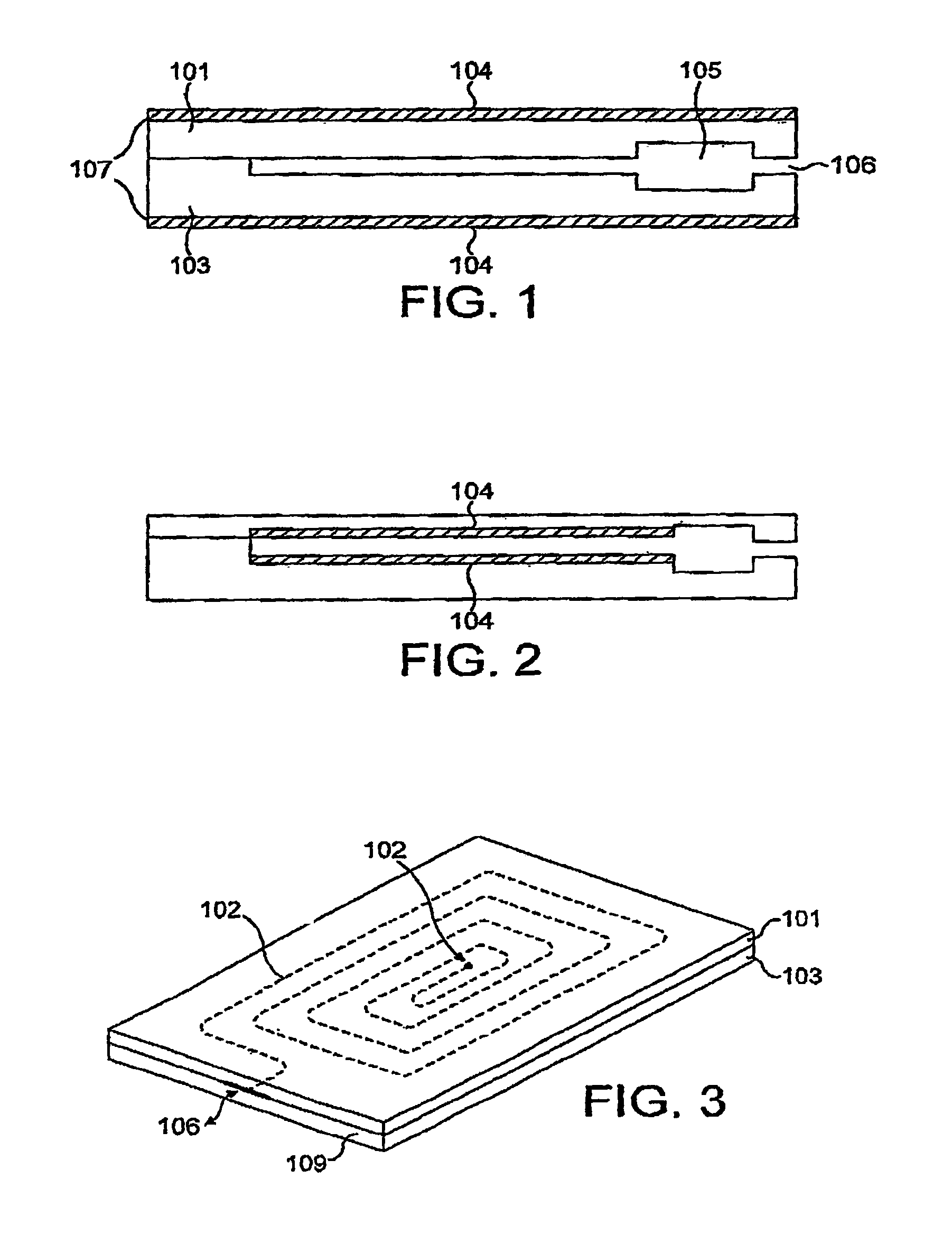
[0082]As shown in FIG. 1, there is provided a disposable test-strip 100 comprising an upper and lower support 101 and 103. A microchannel 102 is formed into the upper surface of the lower support member 103. A upper support member 101 is laminated on top of the support member 103, thereby closing the open microchannel 102. Electrodes 104 are formed on the respective outer surfaces of the substrate layers and coplanar to the channel. The electrodes may run along the entire outer length to an edge of the device as shown in FIG. 1a, so that suitable electrical contact may be made between the leads and the meter (not shown).. The electrodes themselves may be covered by a further laminate in order to protect them. Also shown is a reservoir 105 into which the sample initially flows and a sample inlet port 106. As shown, the inlet port is substantially level with the microchannel and the sample reservoir fills by capillary action. However the sample inlet port may be situated above the dev...


PUM

PropertyMeasurementUnit
lengthaaaaaaaaaa
volumeaaaaaaaaaa
widthaaaaaaaaaa

Abstract

A device and method for measuring clotting times in a fluid, typically blood, within a microchannel, with the onset of clotting being determined by measurement of the rate of change, or the value, of capacitance or impedance between two electrodes situated on either side of the microchannel. The device includes an upper support member and a lower support member with a microchannel formed therein. The device also includes electrodes situated along the length of the microchannel.

Description

[0001]This application claims the benefit of PCT Application No. PCT / GB01 / 05644 filed Dec. 19, 2001, which claims priority from Great Britain Application No. GB0030929.4 filed Dec. 19, 2000.FIELD OF INVENTION[0002]The present invention relates to a device and method for measuring the coagulation factors of a biological sample. More specifically, the invention relates to a disposable test-strip to be inserted into a hand-held or portable meter which is able to display the results of the coagulation assay. Such a device is suitable for home-testing or point of care.BACKGROUND OF THE INVENTION,[0003]The ability of the body to arrest the flow of blood following vascular injury is paramount to continued survival. The process by which this occurs is termed haemostasis and is accomplished by the process of blood coagulation leading to formation of a blood clot or thrombosis. A blood clot consists of a plug of platelets enmeshed in a network of insoluble fibrin particles. Whilst formation o...

Claims


Application Information

Patent Timeline
Patent Type & Authority Patents(United States)
IPC IPC(8): G01N27/02G01R27/08A61B5/15A61B5/00A61B5/1468A61B5/151A61B10/00G01N27/22G01N33/49G01N33/86
CPCA61B5/1473A61B5/14514A61B10/0045A61B5/1411A61B2010/008A61B5/150022A61B5/150213A61B5/150358A61B5/150419A61B5/15045A61B5/150755A61B5/15142
Inventor STIENE, MATTHIASRICHTER, TANJAMCALEER, JEROMEPLOTKIN, ELLIOTALVAREZ-ICAZA, MANUELALLEN, JOHN
Owner LIFESCAN IP HLDG LLC
Why Eureka
Try Eureka