
Low power serializer circuit and method

a low-power serializer and circuit technology, applied in the field of electronic circuitry, can solve the problem that no latch may be coupled to the other input of the multiplexer

Inactive Publication Date: 2006-02-28
RPX CORP
View PDF4 Cites 54 Cited by
  • Summary
  • Abstract
  • Description
  • Claims
  • Application Information

AI Technical Summary

Benefits of technology

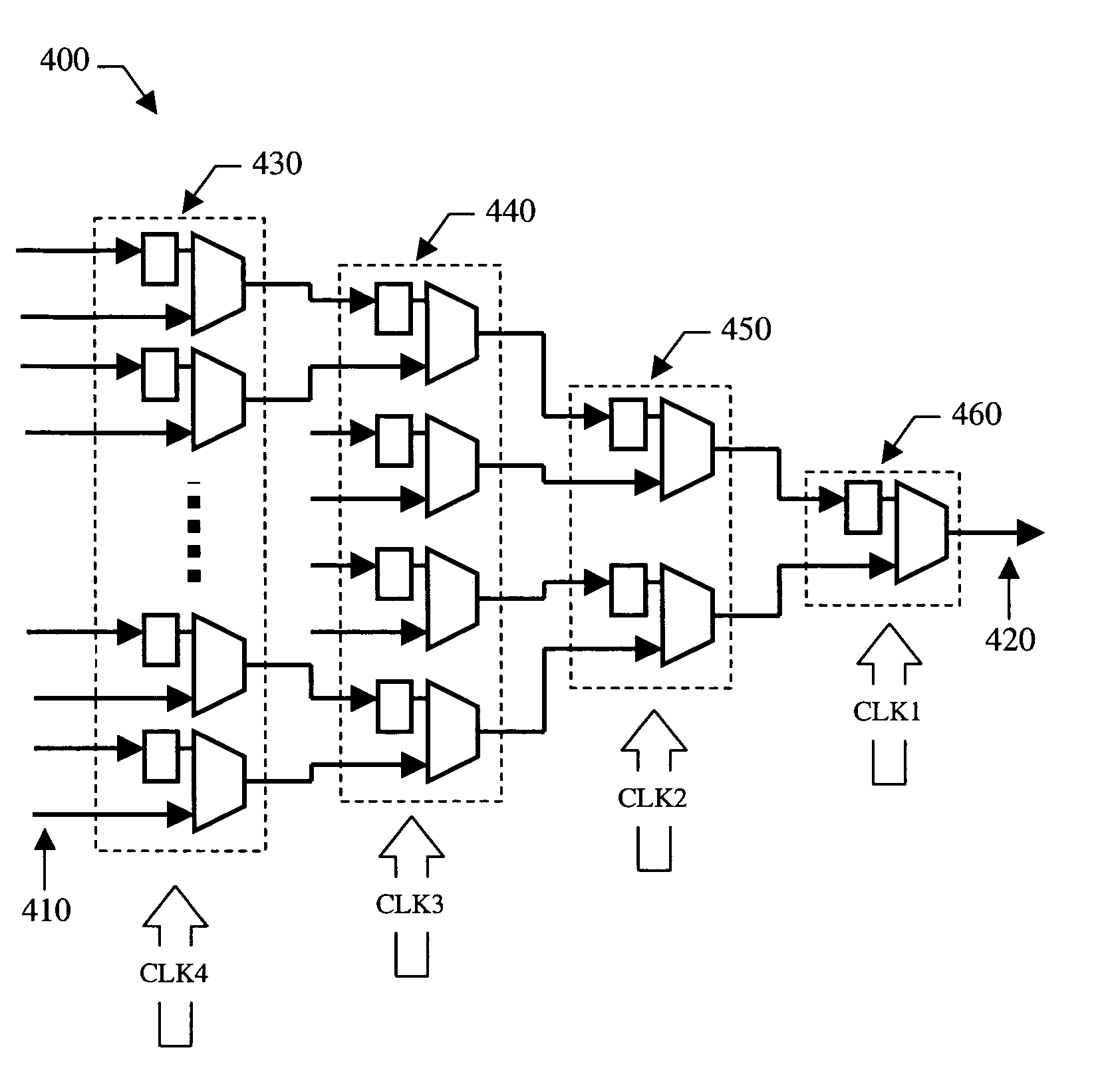
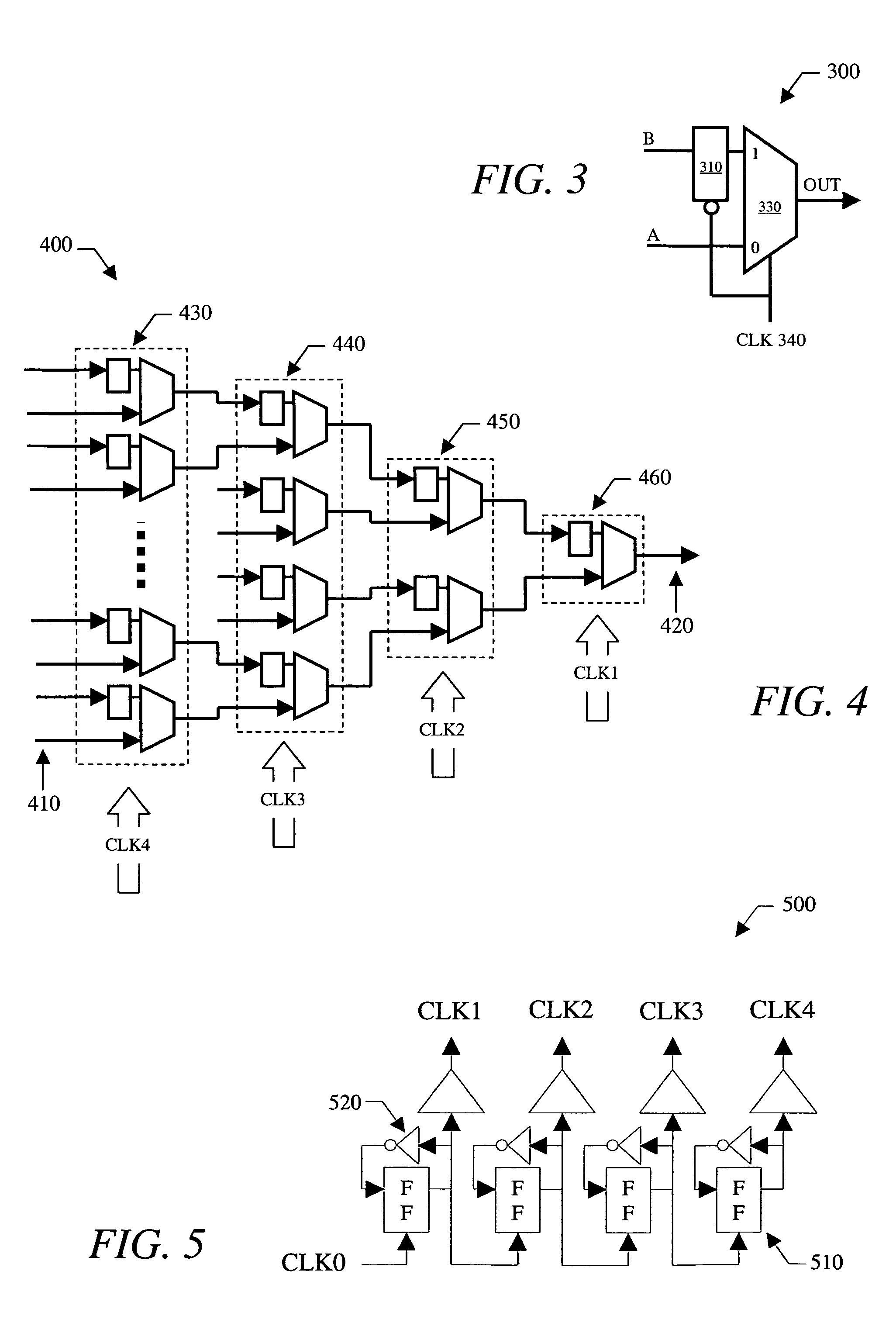
[0019]To serialize the parallel bitstreams, the step of generating a third bitstream may include receiving a rising edge of the second clock signal at the third multiplexing cell, on or before receiving a rising edge of the first clock signal at the first and second multiplexing cells. The rising edge of the first clock signal may enable a first bit value to be propagated to the input of the latch of the third multiplexing cell, while a second bit value is set up at a second input to the multiplexer of the third multiplexing cell. After the rising edge of the first clock signal is received, a falling edge of the second clock signal may be received at the third multiplexing cell. Successful pipeline operation can be ensured by guaranteeing that a rising clock edge in any given stage of the pipeline can only be followed by a falling clock edge in a subsequent (and therefore, faster) stage of the pipeline.
[0021]According to yet another embodiment, a method is provided herein for decreasing power consumption in a pipeline serializer, which arranges a number of multiplexing cells into one or more pipelined stages of the serializer. As noted above, each of the pipelined stages may be adapted to receive an increasingly faster clocking signal. In a general embodiment, the method may include forming each of the multiplexing cells by coupling only one latch to one input of a multiplexer and no latches to another input of the multiplexer. To ensure minimum jitter and power operation (for a given frequency) when only one latch is used per multiplexing cell, the method may also include matching a clock-to-output time delay through the multiplexers residing within a first stage of the serializer, with a clock-to-output time delay through the latches residing within a second stage of the serializer.
[0023]According to yet another embodiment, a method is provided herein for ensuring successful operation of a pipelined serializer, which arranges a number of multiplexing cells into one or more pipelined stages of the serializer. In a general embodiment, the method may include generating a plurality of successively faster clocking signals, and supplying each of the plurality of clocking signals to one of the pipelined stages, such that a rising edge of a given clocking signal can only be followed in time by a falling edge of a clocking signal supplied to a next pipeline stage. In some cases, the step of supplying may further ensure that a falling edge of a given clocking signal can only be followed in time by a falling edge of a clocking signal supplied to the next pipeline stage.

Problems solved by technology

However, no latches may be coupled to the other input of the multiplexer.

Method used


Image

  • Low power serializer circuit and method
  • Low power serializer circuit and method
  • Low power serializer circuit and method

Examples


Embodiment Construction

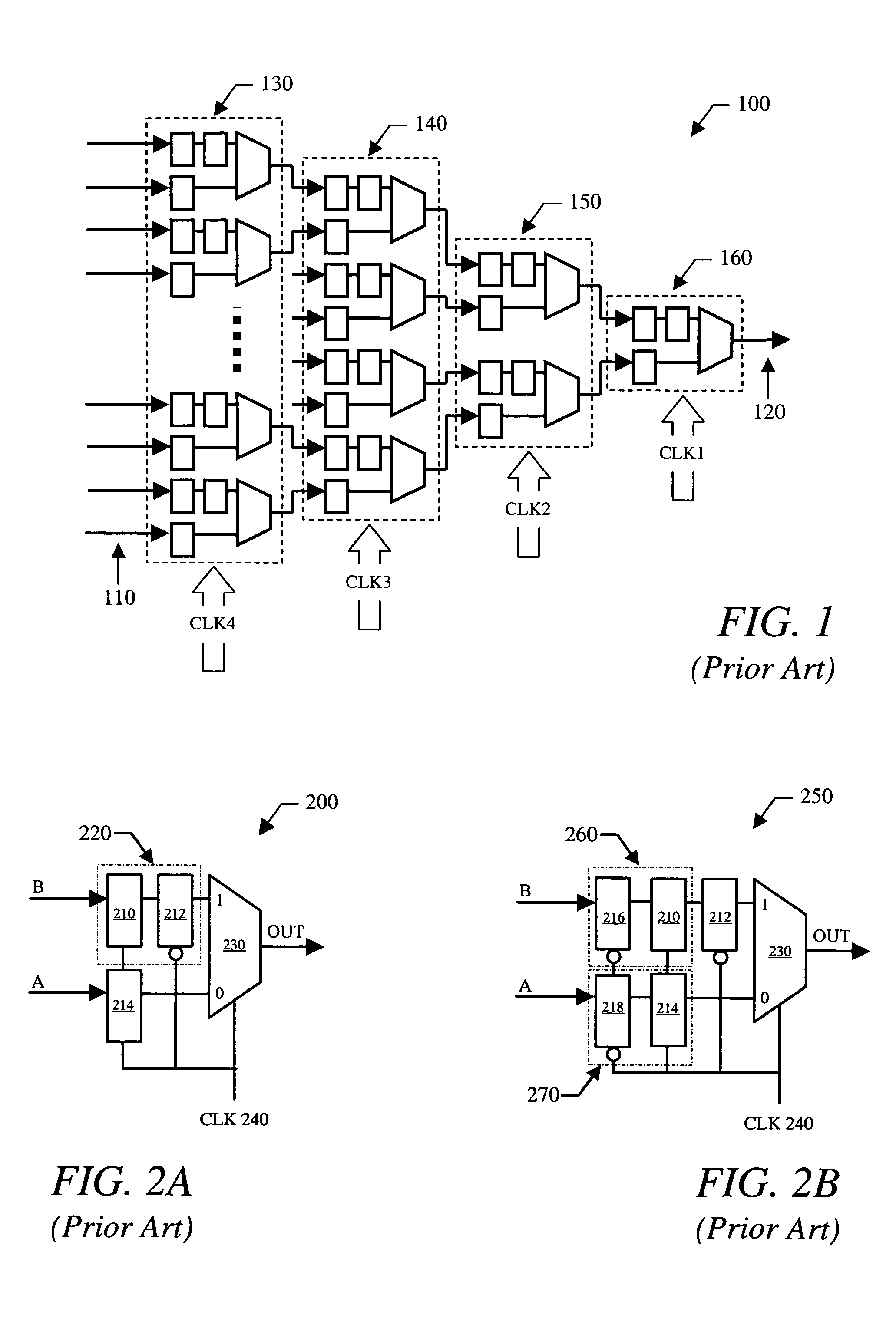
[0035]A pipelined serializer is, in principle, a “pipelined multiplexer” constructed from a “binary tree” of “registered multiplexer” building blocks to form a serializer core with log2(n) stages of pipelining, given an input word of length n. In general, pipelined serializers aim to reduce power consumption by reducing the number of circuit elements clocked at the “serial data rate,” or the speed at which a serial bitstream is transferred between transmitting and receiving components of a system. The serial data rate may also be referred to as the “bit transfer rate.” Pipelined serializers are typically constructed by arranging a plurality of multiplexing cells into stages, where each successive stage is clocked by a correspondingly faster clock rate. The opposite holds true for pipelined deserializers (i.e., each stage may be clocked by a successively slower clock rate). Since power efficiency tends to increase with decreasing speed, use of a pipelined serializer / deserializer gene...


PUM


Abstract

A serializer within, for example, a transceiver is provided having multiple stages of pipelined multiplexing cells. Each multiplexing cell may be substantially the same and each comprises no more than one latch. In some embodiments, each multiplexing cell includes a multiplexer comprising a pair of inputs and a single latch, which is coupled to one input of the multiplexer. No latches are coupled to the other input of the multiplexer. The serializer generally includes a plurality of stages. Each successive stage includes one-half the number of multiplexing cells included in the previous stage, and each successive stage is clocked by a clocking signal that transitions at twice the frequency of the previous stage clock signal.

Description

PRIORITY CLAIM[0001]This application claims benefit of priority to a provisional patent application Ser. No. 60 / 482,933 entitled “Low Power Serializer Circuit and Method,” filed Jun. 27, 2003, which is hereby incorporated in its entirety.BACKGROUND OF THE INVENTION[0002]1. Field of the Invention[0003]This invention relates to electronic circuitry and, more particularly, to a serializer that contains multiple multiplexing cells arranged in stages, where each cell contains fewer circuit elements and consumes less power than conventional multiplexing cells.[0004]2. Description of the Related Art[0005]The following descriptions and examples are given as background only.[0006]Communication between nodes of a communication system typically involves a serial bitstream. The bitstream can be formatted in numerous ways and is sent across a wire or wireless medium between nodes of the network. Examples of serial bitstream transfer protocols include Ethernet and Synchronous Optical Network (“SO...

Claims


Application Information

Patent Timeline
IPC IPC(8): H03M9/00
CPCH03M9/00G06F7/68
Inventor LOMBAARD, CAREL J
Owner RPX CORP
Learn More