
Diffraction grating based interferometric systems and methods

a technology of interferometer and grating, which is applied in the field of diffraction grating based interferometer, can solve the problems of sample light beam suffering a significant loss of energy, sample light beam suffering a high loss of energy, and reference light beam suffering a further loss of about 50

Inactive Publication Date: 2006-02-28
BOSTON SCI SCIMED INC
View PDF12 Cites 305 Cited by
  • Summary
  • Abstract
  • Description
  • Claims
  • Application Information

AI Technical Summary

Benefits of technology

[0013]Preferably, the reference light beam is diffracted and the sample light beam is directed onto the second beam splitter without being diffracted. By only diffracting the reference light beam and combining the sample light beam with the diffracted reference light beam on a second beam splitter, the sample light beam does not suffer from loss and noise due to interacting with the diffraction grating.

Problems solved by technology

The sample beam typically suffers a high loss of energy due to its interaction with the sample.
The sample light beam suffers a significant loss of energy due to its interaction with the sample.
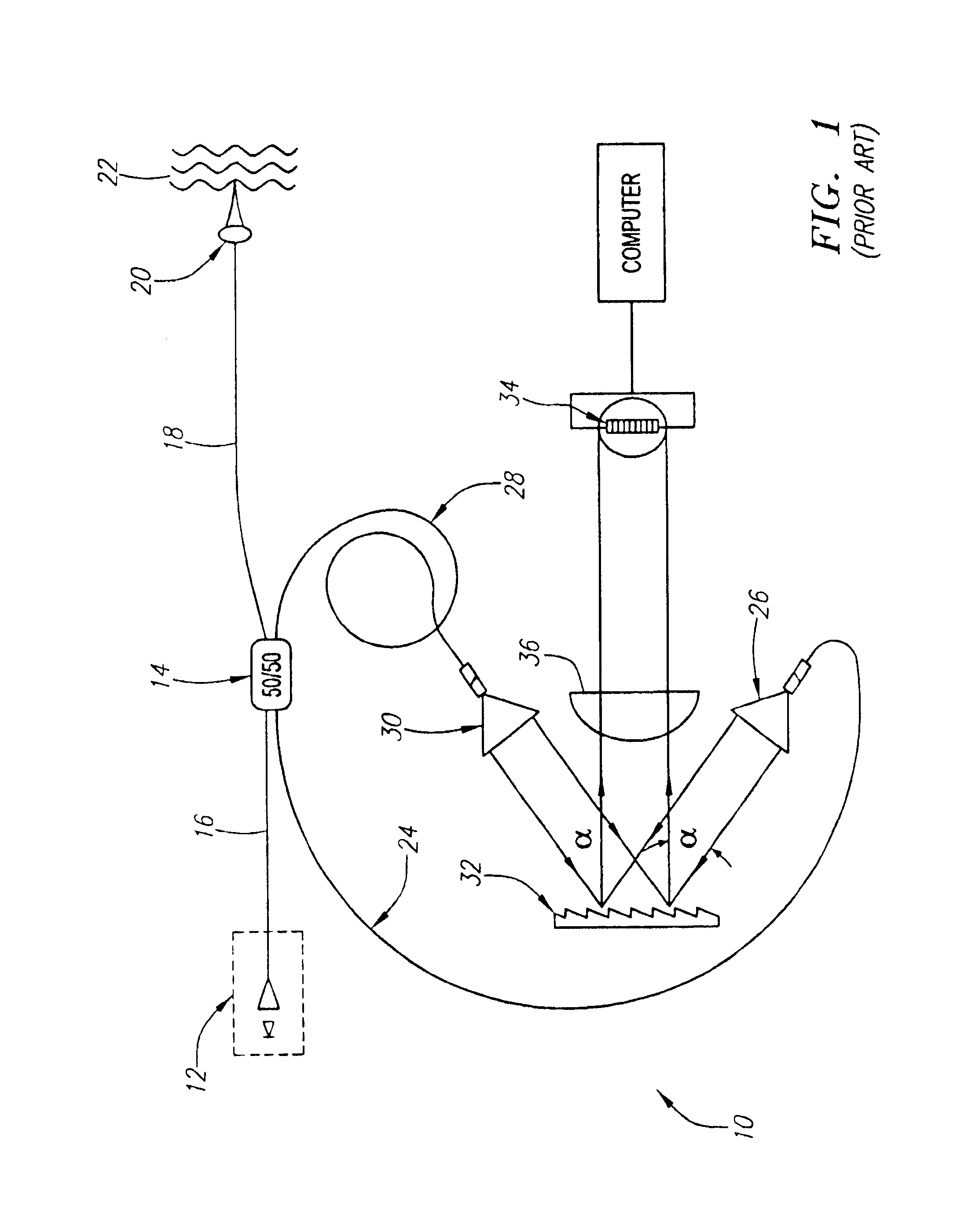
In addition, the interaction of the light beams with the diffraction grating causes a further loss in both the sample light beam and the reference light beam of about 50% of the incident light in the first order.
The diffraction grating also introduces noise.
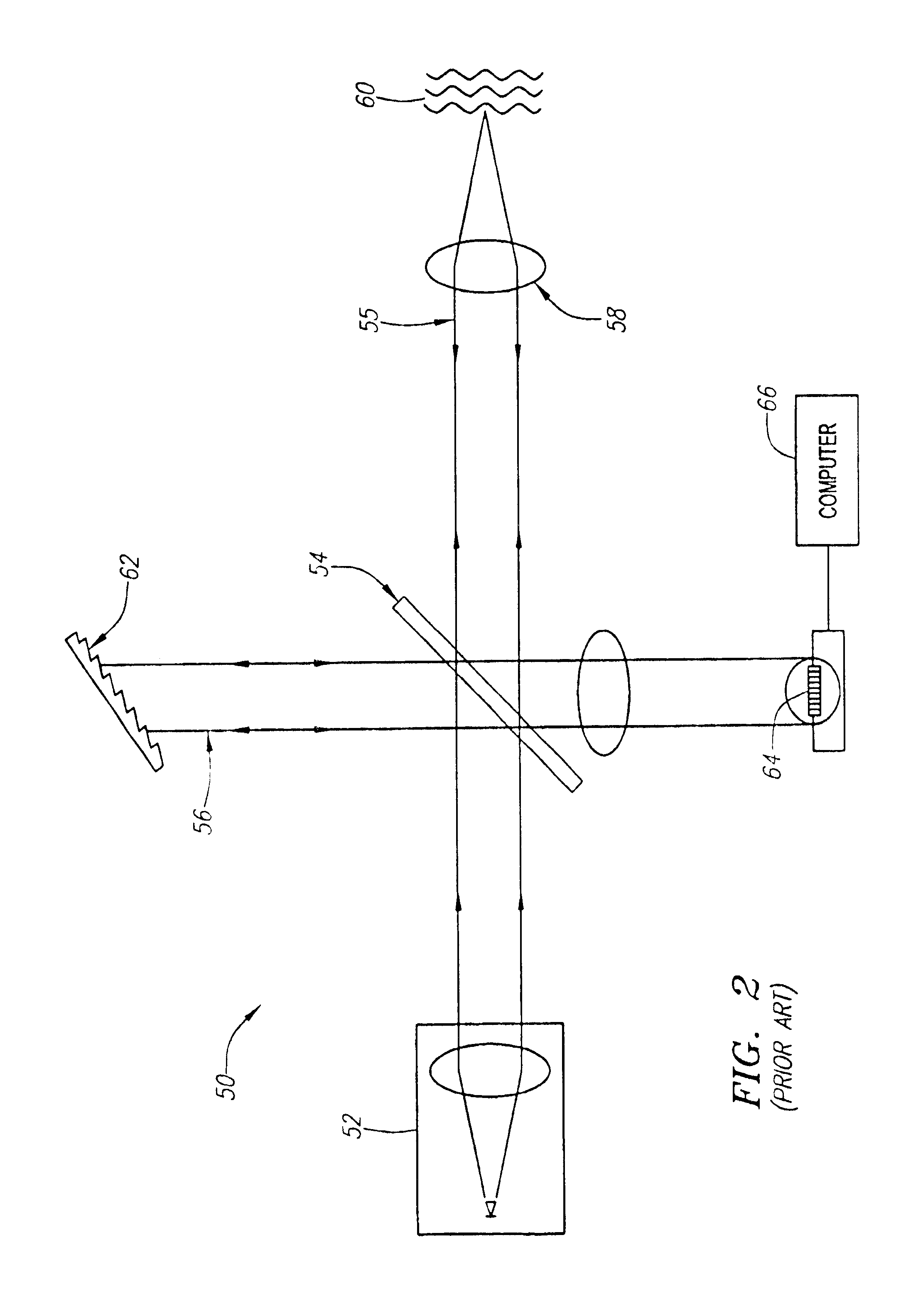
However, the sample and reference arms in the system 50 of FIG. 2 cannot both be implemented with fiber optics.
If the sample arm is implemented in fiber optics but the reference arm is not, the length of the open space reference arm would be inconveniently long.
Providing a separate modulating unit in the interferometer takes up additional space and adds to the complexity of the system.
Such energy is lost in the system.
The sample light beam also suffers loss and noise if it is diffracted by the diffraction grating.

Method used


Image

  • Diffraction grating based interferometric systems and methods
  • Diffraction grating based interferometric systems and methods
  • Diffraction grating based interferometric systems and methods

Examples


Embodiment Construction

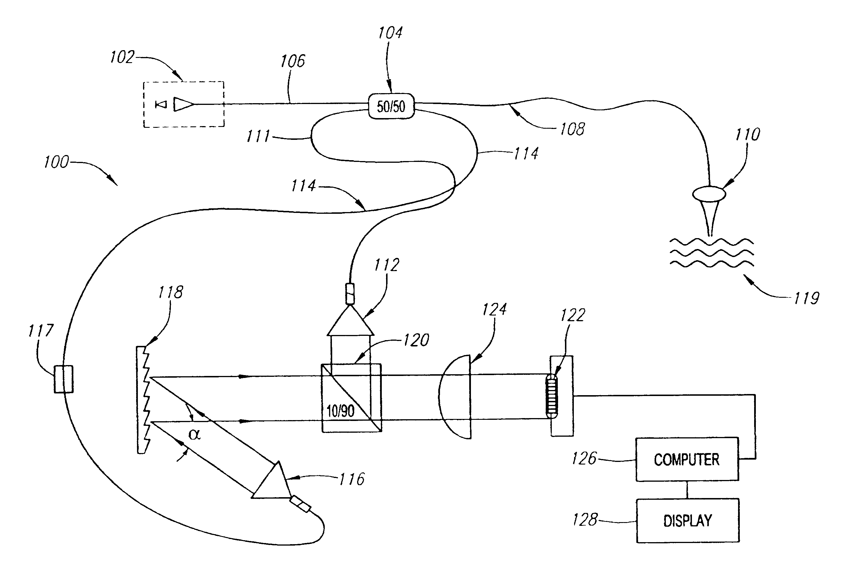
[0039]FIG. 3a is a schematic diagram of one embodiment of a diffraction grating based fiber optic interferometric system 100. The system 100 comprises a light source 102 optically coupled to a fiber optic beam splitter 104 by an optical fiber 106. The fiber optic beam splitter 104 is preferably approximately a 50 / 50 beam splitter. More preferably, the beam splitter 104 is a 50 / 50 beam splitter. An optical fiber 108 is optically coupled to the fiber optic beam splitter and to a focusing lens 110.

[0040]An optical fiber 111 is also optically coupled to the fiber optic beam splitter 104 such that light entering the beam splitter from the optical fiber 108 is coupled into the optical fiber 110. The optical fiber 111 is also optically coupled to a first collimator 112. Another optical fiber 114 is optically coupled to the first beam splitter 104 and to a second collimator 116.

[0041]The optical fibers 108 and 110 comprise first and second parts of a sample arm, respectively, of the interfe...


PUM


Abstract

Diffraction grating based fiber optic interferometric systems for use in optical coherence tomography, wherein sample and reference light beams are formed by a first beam splitter and the sample light beam received from a sample and a reference light beam are combined on a second beam splitter. In one embodiment, the first beam splitter is an approximately 50 / 50 beam splitter, and the second beam splitter is a non 50 / 50 beam splitter. More than half of the energy of the sample light beam is directed into the combined beam and less than half of the energy of the reference light beam are directed into the combined beam by the second beam splitter. In another embodiment, the first beam splitter is a non 50 / 50 beam splitter and the second beam splitter is an approximately 50 / 50 beam splitter. An optical circulator is provided to enable the sample light beam to bypass the first beam splitter after interaction with a sample. Two combined beams are formed by the second beam splitter for detection by two respective detectors. More than half of the energy of the light source provided to the first beam splitter is directed into the sample light beam and less than half of the energy is directed into the reference light beam. The energy distribution between the sample and reference light beams can be controlled by selection of the characteristics of the beam splitters.

Description

RELATED APPLICATION[0001]The present application is related to U.S. patent application Ser. No. 10 / 020,040, titled “SYSTEMS AND METHODS FOR PROCESSING SIGNALS FROM AN INTERFEROMETER BY AN ULTRASOUND CONSOLE” filed on the same day as the present application, assigned to the assignee of the present application and incorporated by reference herein.FIELD OF THE INVENTION[0002]This invention relates generally to diffraction grating based interferometers and, more particularly, to diffraction grating based interferometric systems for use in optical coherence tomography.BACKGROUND OF THE INVENTION[0003]Optical Coherence Tomography (“OCT”) is a type of optical coherence-domain reflectometry that uses low coherence interferometry to perform high resolution ranging and cross-sectional imaging. In OCT systems, a light beam from a low coherence light source is split into a reference light beam and a sample light beam. A diffraction grating may be used to provide an optical path difference in on...

Claims


Application Information

Patent Timeline
Patent Type & Authority Patents(United States)
IPC IPC(8): G01B9/02
CPCG01N21/4795G01B9/02007G01B9/02029G01B9/02044G01B9/02091G01B9/02032G01B9/02002G01B2290/45G01B2290/70
Inventor OSTROVSKY, ISAACMODELL, MARK D.CROWLEY, ROBERT J.
Owner BOSTON SCI SCIMED INC
Learn More