Wireless point to multi-point communication apparatus and method

a multi-point communication and wireless technology, applied in transmission monitoring, high-level techniques, sustainable buildings, etc., can solve the problems of limiting the rate the rate limiting component of data transfer and communication, and the limited rate of data transfer. achieve the effect of more energy-efficient point-to-multi-point communication

Inactive Publication Date: 2006-02-28
ENDWAVE CORP
View PDF5 Cites 13 Cited by
  • Summary
  • Abstract
  • Description
  • Claims
  • Application Information

AI Technical Summary

Benefits of technology

[0013]Accordingly, it is an object of the present invention to provide a wireless communication system (WCS) that achieves more energy efficient point to multi-point communication.

Problems solved by technology

This rate of data transfer is limited by the inherent properties of copper wire and its use throughout LTNs.
Since the inception of computer mediated data transfer, data transfer rates were limited by processor speeds and not by the mode or medium of data transfer.
This creates a situation where the LTN (and DSL) are far slower than processors and thus the rate limiting component of data transfer and communication.
While fiber optic systems provide favorable data transfer rates, one disadvantage aspect is that fiber optic systems are extremely expensive to install.
In urban areas, for example, the cost of burying cable is approximately one million dollars per mile.
A relative disadvantage of microwave systems, however, is that they have a significantly smaller bandwidth then millimeter wave and fiber optic systems.
Notwithstanding their higher bandwidth, however, millimeter wave systems are disadvantageous in that they are susceptible to rain fade and other atmospheric conditions, requiring significantly larger power transmitters to assure sufficient signal strength in foul weather.
A disadvantage of fan out, fan back wireless systems, however, is that link margin is reduced by 15 to 20 dB compared to the fan out, pencil back arrangement of the present invention.
To overcome link margin deficiencies, these systems utilized large and expensive power transmitters at the customer premises equipment (CPEs).
Since the customer equipment is mass produced, customer equipment that is expensive and inefficient can be crippling to efforts to introduce an emerging communication technology.
Efforts to overcome link margin deficiencies also resulted in the use of higher gain, more expensive antennas at the hub.

Method used


Image

  • Wireless point to multi-point communication apparatus and method
  • Wireless point to multi-point communication apparatus and method
  • Wireless point to multi-point communication apparatus and method

Examples


Embodiment Construction

taken together with the drawings.

BRIEF DESCRIPTION OF THE DRAWINGS

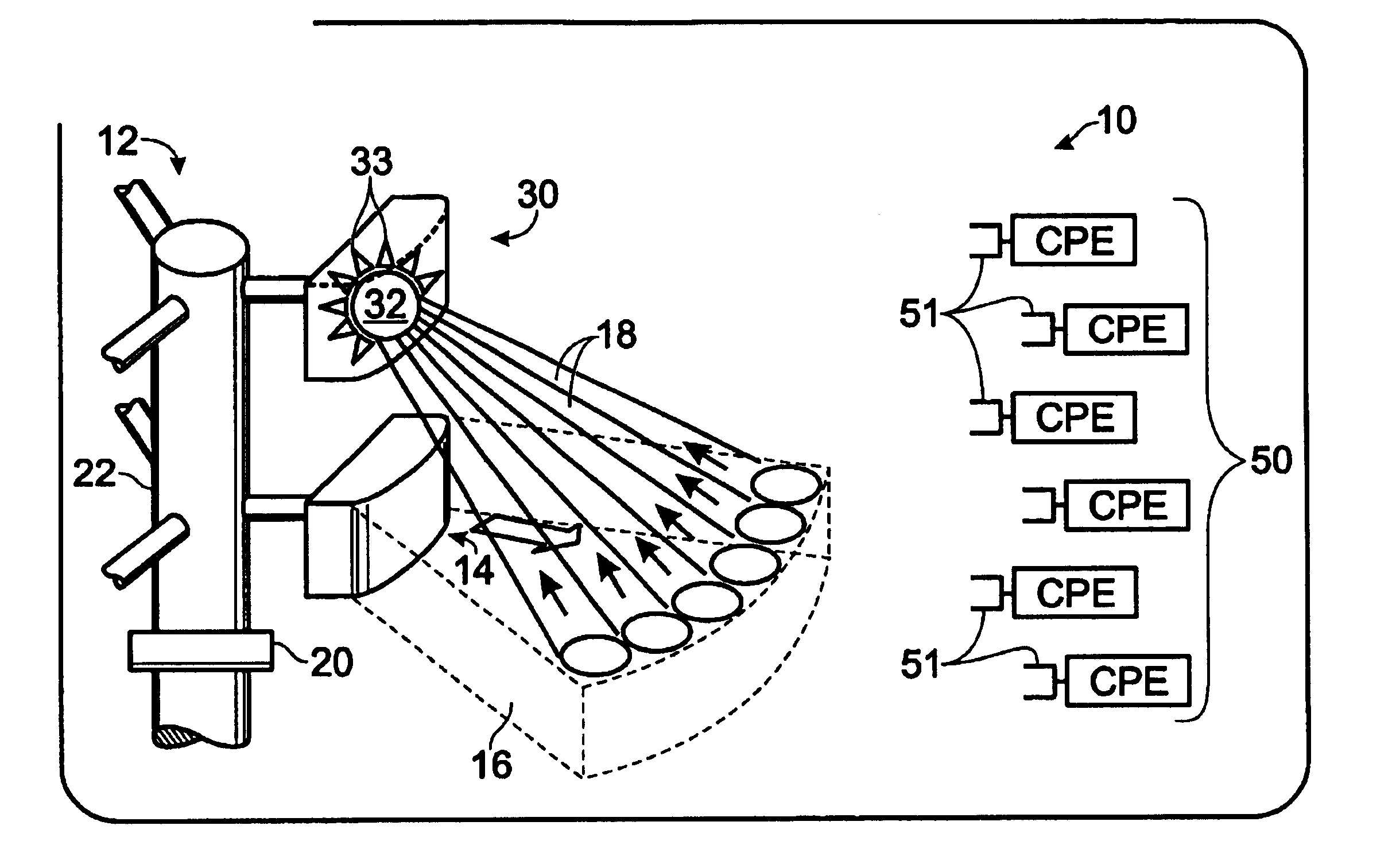
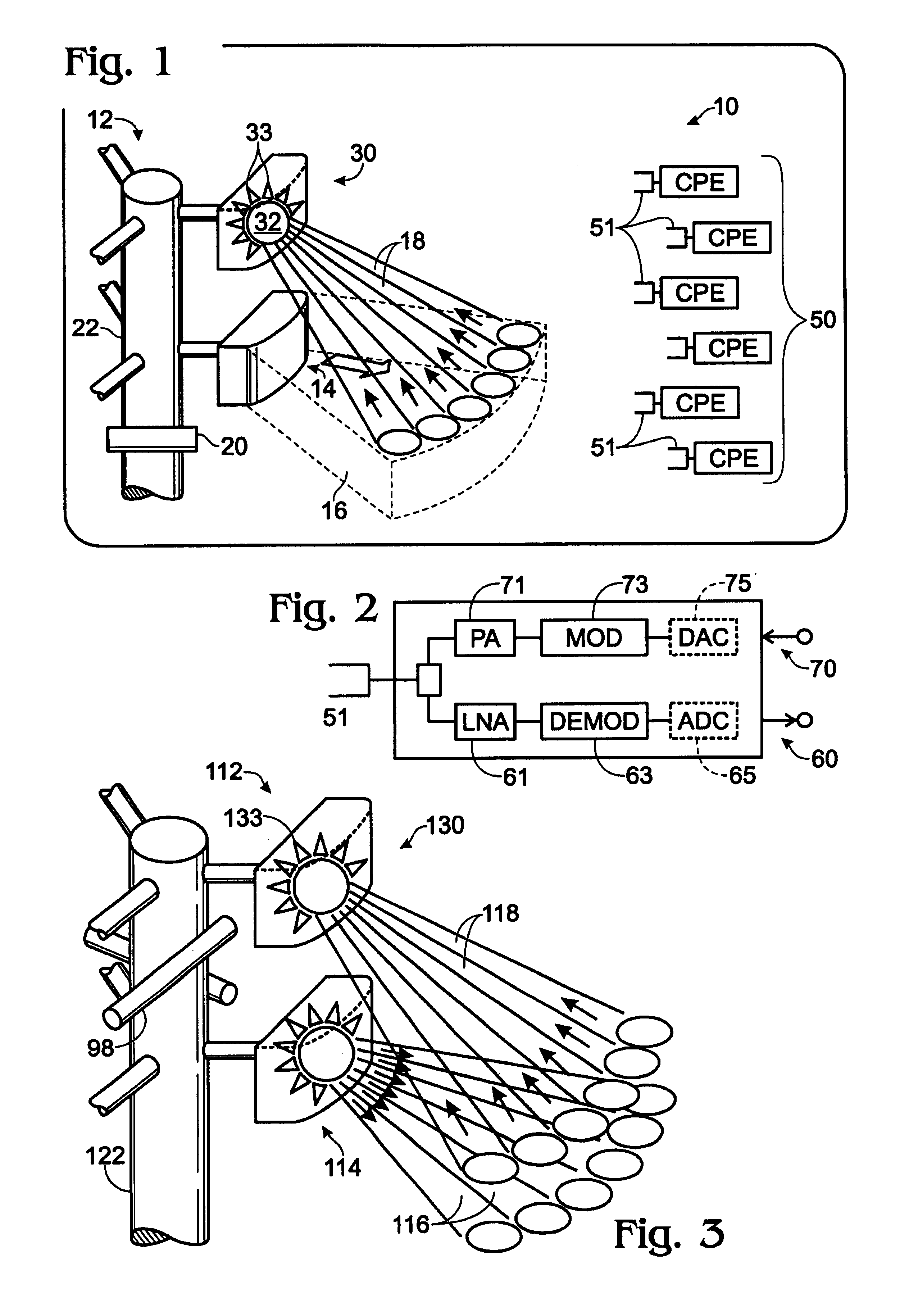
[0023]FIG. 1 is a diagram of a wireless point to multi-point communication system in accordance with the present invention.

[0024]FIG. 2 is a schematic block diagram of receive and transmit circuitry within customer premises equipment in accordance with the present invention.

[0025]FIG. 3 is a diagram of an alternative hub arrangement for a WCS in accordance with the present invention.

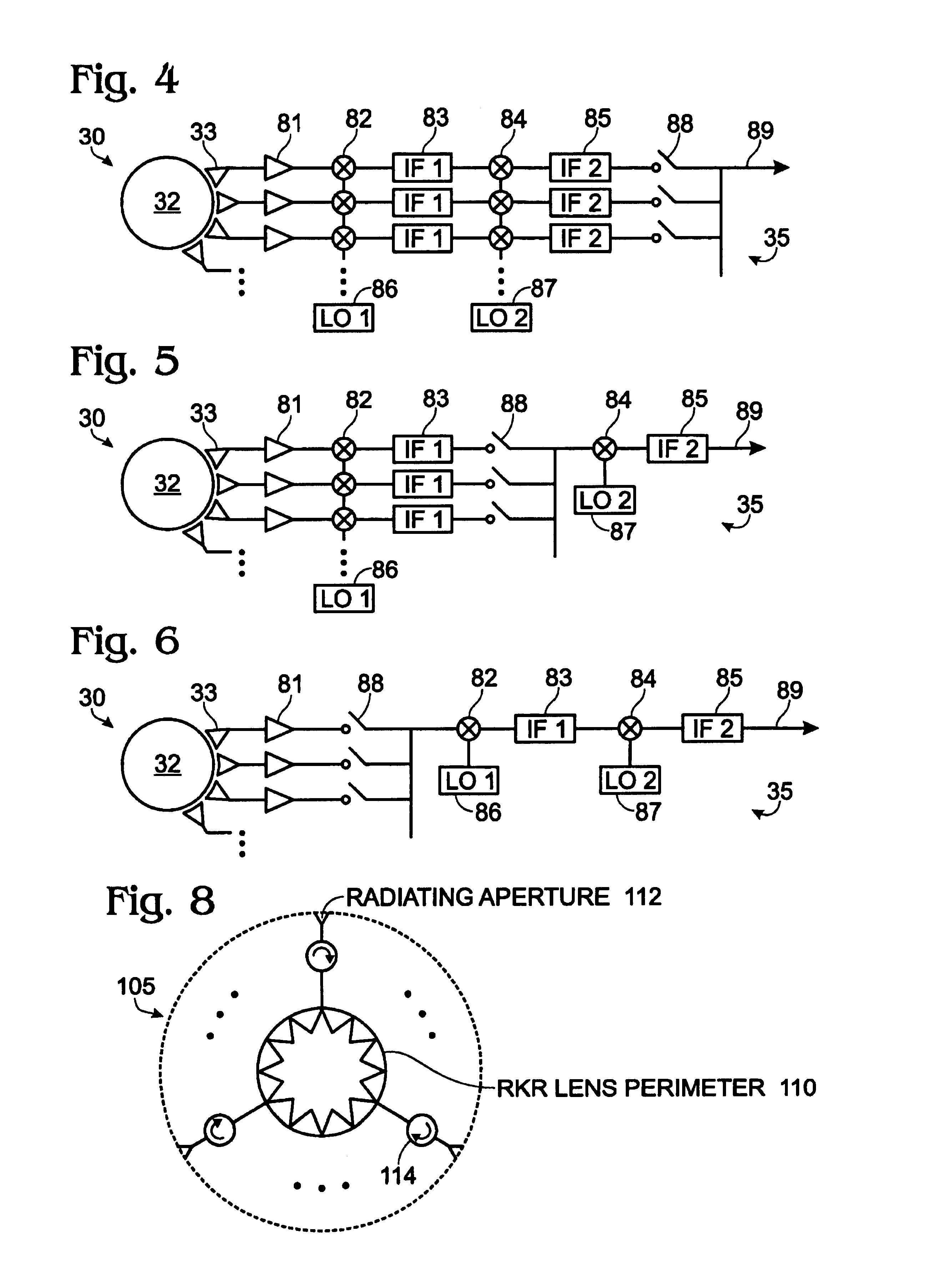
[0026]FIGS. 4-6 are schematic block diagrams of embodiments of processing circuitry for a shared aperture receive antenna mechanism in accordance with the present invention.

[0027]FIG. 7 is a diagram illustrating an implementation of a WCS in accordance with the present invention.

[0028]FIGS. 8-9 are diagrams of alternative antenna arrangements in accordance with the present invention.

DETAILED DESCRIPTION

[0029]Referring to FIG. 1, a diagram of a point to multi-point wireless communication system (WCS) 10 in accordance with the present invent...


PUM


Abstract

A wireless communication system that provides energy efficient, high bandwidth and low cost wireless communication. In one embodiment, the communication system utilizes a fan out, pencil beam arrangement in which electro-magnetic energy is transmitted from a hub to customer premises equipment (CPE) with a fan or similar antenna and from the CPEs to the hub via pencil beam antennas. The pencil beam antennas provided higher link margin. The hub may include a shared aperture antenna device for receiving pencil beam transmissions from the CPEs. A shared aperture antenna device may also be used for transmission from the hub to the CPEs.

Description

FIELD OF THE INVENTION[0001]The present invention relates to wireless communication systems and is particularly well suited to millimeter wave communication systems. More specifically, the present invention is related to providing energy efficient, low-cost point to multi-point wireless communication.BACKGROUND OF THE INVENTION[0002]Conventional legacy telephone networks (LTNs) use copper wire for data transfer and achieve data transfer rates of approximately 28 Kbits (KB) per second. This rate of data transfer is limited by the inherent properties of copper wire and its use throughout LTNs. Digital subscriber lines (DSLs) are available in some communities and DSL technology piggy backs on legacy copper wires and achieves data transfer rates of one or two MB.[0003]The current push for faster phone and data lines has in part been fueled by advances in microprocessor technologies and the ability of computers to share data with one another. The development and growth of the Internet is...

Claims


Application Information

Patent Timeline
Patent Type & Authority Patents(United States)
IPC IPC(8): H04B15/00
CPCH04B7/0408Y02B60/50Y02D30/70
Inventor LOCKIE, DOUGLAS G.KEIBLE, EDWARD A.MOHWINKEL, CLIFFORD A.
Owner ENDWAVE CORP
Why Eureka
Try Eureka