Automated livestock trough

a technology troughs, which is applied in the field of automatic watering troughs, can solve the problems of inconvenient operation, high labor intensity, and inconvenient use of manual labor required to deliver water to the troughs, and achieves the effects of convenient use and maintenance, simple construction, and convenient a plurality of uses

Inactive Publication Date: 2006-03-07
USA TIRE MANAGEMENT SYST
View PDF8 Cites 21 Cited by
  • Summary
  • Abstract
  • Description
  • Claims
  • Application Information

AI Technical Summary

Benefits of technology

[0013]Still another object of the present invention is to provide an automated watering trough that is relatively simple in construction.
[0014]Yet another object of the present invention is to provide an automated watering trough that is easily adapted for a plurality of uses in different settings and environments.
[0015]A further object of the present invention is to provide an automated watering trough that is easy to use and maintain.

Problems solved by technology

However, the manual labor required to deliver water to the troughs expends valuable time and, depending on the location of the trough, can be a significant inconvenience.
However, those attempts typically resulted in watering troughs that were either too complex and costly to operate or troughs that repeatedly failed to perform their automated function.
Oftentimes, the failure of an automated water trough is due to component damage caused by livestock or the elements.
As livestock repeatedly come into contact with water supply lines, valves and other such structures, the automated system invariably becomes damaged and fails over time.
Harsh winters and dry, hot summers will also wear down component systems, if not causing them to fail suddenly.

Method used


Image

  • Automated livestock trough
  • Automated livestock trough
  • Automated livestock trough

Examples


Embodiment Construction

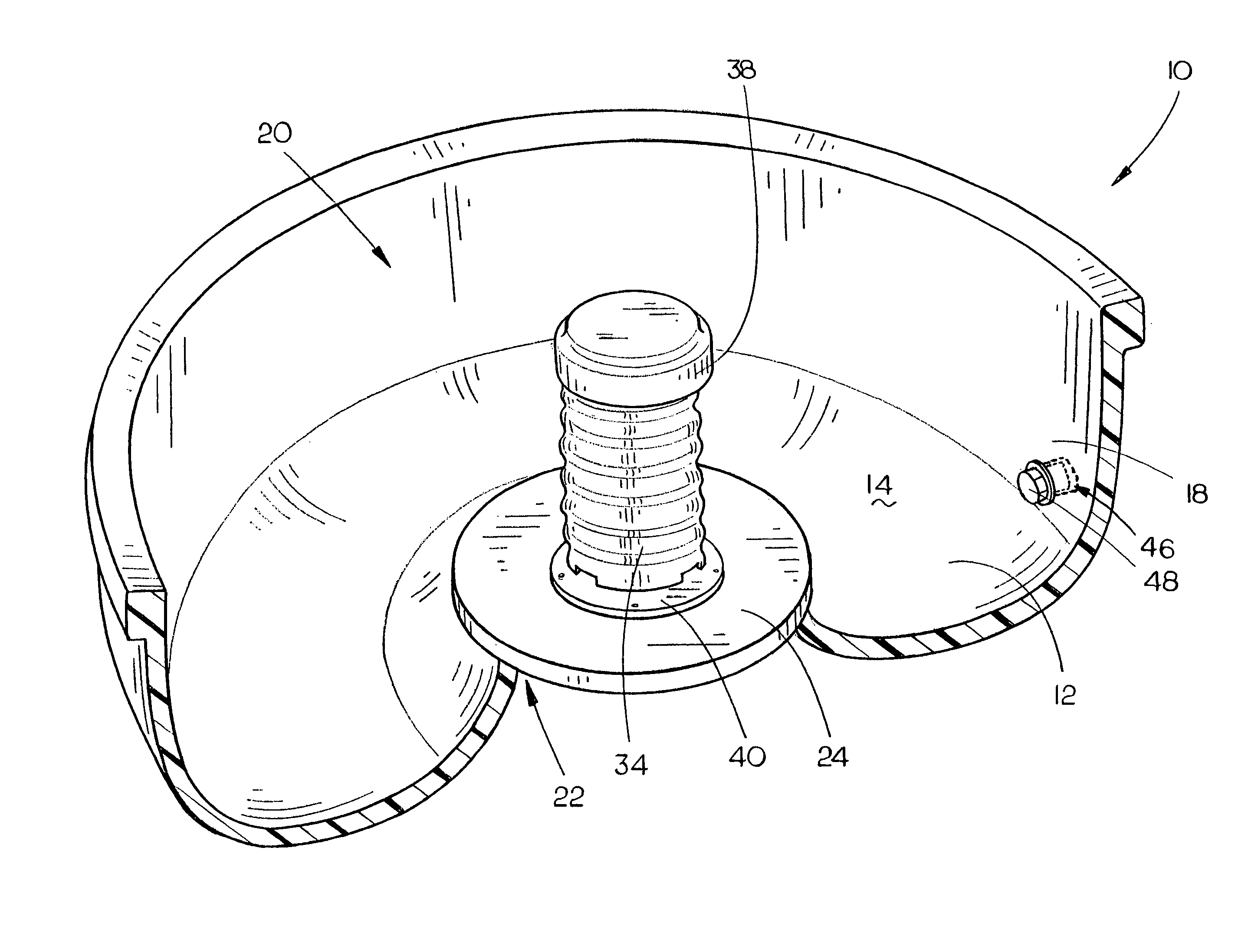
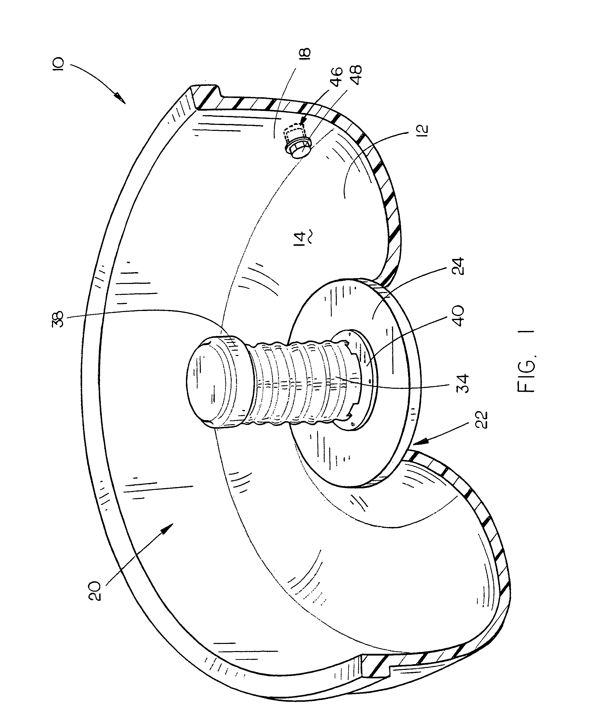
[0021]The livestock trough 10 of the present invention is generally depicted in FIGS. 1–4. The trough 10 is provided with a base 12 having an upper surface 14 and a lower surface 16. A wall 18 extends upwardly from the peripheral edge portion of the base 12 to form an open cavity 20. It is contemplated that the base 12 and wall 18 could be formed from nearly any material, so long as the material is suitable for extended periods of contact with water. For example, the trough could be formed from metal, such as the ubiquitous round or ovular metal water troughs that are frequently used for watering livestock. The shape of the trough is relatively unimportant and may be configured to fit any particular application. It is preferred, however, that the trough be sized and shaped to support a sufficient volume of water to support the livestock for which it is intended.

[0022]In a preferred embodiment, the trough is comprised of a recycled over-the-road tire having one of its sidewalls remov...


PUM


Abstract

An automated watering trough is provided with a fluid supply line that automatically fills the trough to a desired volume through the use of a valve and actuator. A protective housing may be provided to substantially encase the valve and actuator, along with an optional overflow conduit, to reduce the incidence of contact between livestock and the automation components. The shell of the trough may be comprised of a recycled tire provided with a base plug, which may support the protective tower and automation components.

Description

BACKGROUND OF THE INVENTION[0001]1. Field of the Invention[0002]The present invention relates to troughs for use in watering livestock, and more particularly to a trough that automatically maintains a selected volume of water and substantially resists damage to its operative components by livestock.[0003]2. Description of the Prior Art[0004]Watering troughs are widely used by livestock producers who raise their livestock in grazing paddocks that do not have natural water sources such as streams or ponds. The use of water troughs is also frequently used for the exclusion of livestock from natural bodies of water. Some water troughs take the form of a simple holding tank that is placed in the pasture and must be manually filled with water that is brought to the trough from a remote source. Some troughs are positioned adjacent to a water source that must be manually actuated, such as a hand pump that is coupled with a well. However, the manual labor required to deliver water to the tro...

Claims


Application Information

Patent Timeline
Patent Type & Authority Patents(United States)
IPC IPC(8): A01K7/04
CPCA01K7/04
Inventor PEDERSON, LES
Owner USA TIRE MANAGEMENT SYST
Why Eureka
Try Eureka