High-speed controlling device

a technology of high-speed control and actuator, which is applied in the direction of electrical control, non-mechanical valves, magnetic bodies, etc., can solve the problem of allowing extremely short switching times, and achieve the effect of short switching times

Inactive Publication Date: 2006-03-07
MAHLE FILTERSYSTEME GMBH
View PDF15 Cites 0 Cited by
  • Summary
  • Abstract
  • Description
  • Claims
  • Application Information

AI Technical Summary

Benefits of technology

[0011]The present invention is concerned with the problem of providing an embodiment for a high-speed actuating device of the type defined in the preamble, so that particularly short switching times can be implemented. In addition, the high-speed actuating device should have a compact design, in particular to thereby make it possible to accommodate the high-speed actuating device in the engine space of a motor vehicle.
[0013]This invention is based on the general idea of designing the high-speed actuating device as a rotational drive in which the armature drives the switching device to execute pivoting adjustments as directly as possible. This is achieved by a rotatably mounted shaft on which both the armature and the switching device are fixedly mounted. Thus, in this design, the switching device is designed to be rotationally adjustable between its two switch positions by rotating about the longitudinal axis of this shaft. Due to the design according to this invention, the masses to be moved by the high-speed actuating device are relatively close to the rotational center of the actuating movement, so that relatively low moments of inertia are achieved on the whole. Smaller moments of inertia promote faster switching times, and at the same time the energy demand for implementation of the short switching times is reduced. The high-speed actuating device can therefore be designed to be compact.
[0016]In a special refinement, the yoke may have a cross section which tapers toward the gap at least in an end section which ends at the gap. As a result of this measure, there is a concentration of the magnetic field lines toward the stop surface in the end section having the tapered cross section, so that the bulging of the magnetic field lines toward the armature can be additionally increased. Thus, this measure also results in an increase in the magnetic attractive forces acting on the armature.
[0017]According to an advantageous refinement, a spring element may be coupled to the shaft, with this coupling taking place in such a manner that in the two switch positions of the switching device, the spring element initiates a restoring torque into the shaft, driving the switching device in the direction of the other switch position, and the spring element does not initiate any restoring torque into the shaft in a middle position of the switching device. Due to this design, the spring element acts more or less as a storage device for potential energy which is fully loaded in both switch positions and manifests its maximum power output to accelerate the armature in switching the electromagnets at the beginning of the rotational adjustment, i.e., at a point in time when the magnetic field must be built up.
[0018]A particularly compact design is obtained when the shaft is designed as a hollow shaft and the spring element is designed as a torsion rod, which extends coaxially in the hollow shaft and is connected to the hollow shaft in a rotationally fixed manner at one end and to a stationary component of the high-speed actuating device in a rotationally fixed manner at the other end. In other words, the torsion rod is rigidly clamped with the end which leads out of the hollow shaft. This design also has the advantage that the torsion rod has a minimum moment of inertia due to its central arrangement in the hollow shaft and thereby maximum accelerations are supported.

Problems solved by technology

However, it would be desirable to have a high-speed adjusting device which can be used much more flexibly and nevertheless permits extremely short switching times.

Method used


Image

  • High-speed controlling device
  • High-speed controlling device
  • High-speed controlling device

Examples


Embodiment Construction

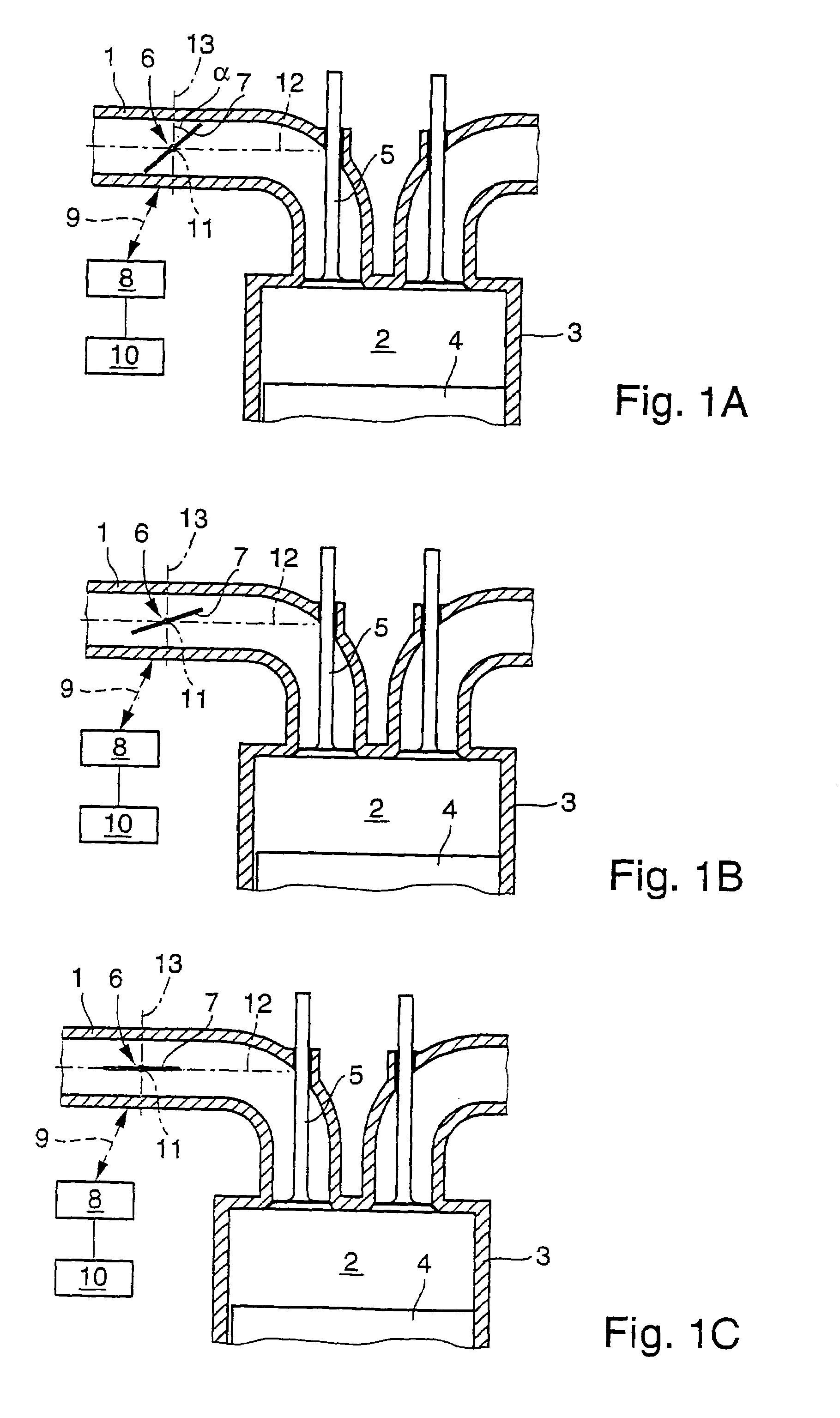
[0030]According to FIGS. 1A through 1C, an engine (not shown in detail), in particular in a motor vehicle, has an intake channel 1 which may also be referred to below as a fresh air supply line. The engine may be designed as a diesel engine or an internal combustion engine as well as an aspirating engine or a supercharged engine. The intake channel 1 leads to at least one combustion chamber 2 of the engine, which is provided in a cylinder 3 in which a piston 4 is mounted so that it has an adjustable stroke. An intake channel 5 is situated at the transition between the intake channel 1 and the combustion chamber 2; likewise, embodiments having a plurality of intake valves 5 are also possible. Upstream from this intake valve 5, an additional valve 6, which is provided in the intake channel 1, may also be referred to below as a switching device. This additional valve or switching device 6 is designed here as a switching flap 7 and may be used, for example, to improve the filling of the...


PUM

PropertyMeasurementUnit
angleaaaaaaaaaa
speedaaaaaaaaaa
areaaaaaaaaaaa

Abstract

The present invention relates to a high-speed controlling device, suitable for displacing a switching element between two positions with very short switching times. Said device comprises two switchable electromagnets, between which an armature, with a driven coupling to the switching element, is arranged. According to the invention, said armature contacts the first electromagnet in the first position of the switching element and contacts the other electromagnet in the second position of the switching element. In order to obtain particularly short switching times for the switching element, the armature can be firmly secured to a shaft, which is rotatably mounted about its longitudinal axis and to which said switching element is also fixed in an axially offset manner in relation to the armature.

Description

CROSS REFERENCE TO RELATED APPLICATIONS[0001]Applicants claim priority under 35 U.S.C. §119 of German Application No. 101 40 706.8 filed Aug. 18, 2001. Applicants also claim priority under 35 U.S.C. §365 of PCT / DE02 / 02992 filed Aug. 16, 2002. The International application under PCT article 21(2) was not published in English.BACKGROUND OF THE INVENTION[0002]1. Field of the Invention[0003]The present invention relates to a high-speed actuating device suitable for actuating a switching device between two switch positions in very short switching times, having the features of the preamble of Claim 1.[0004]2. The Prior Art[0005]In certain applications, a mechanical switching device must be actuated between two switch positions within an extremely short switching time. For example, German Patent DE 37 37 824 A1 describes a method of operating an internal combustion engine. This internal combustion engine has an intake channel leading to at least one combustion chamber of the engine, at lea...

Claims


Application Information

Patent Timeline
Patent Type & Authority Patents(United States)
IPC IPC(8): F02D9/10F02D11/10F01L9/20F02B29/08F02D9/02F02D41/20H01F7/14H01F7/16H02K33/12
CPCF01L9/04F02D9/10H01F7/14H01F7/1638F02B29/083F01L2009/0436F01L2105/00Y02T10/146F01L2305/00Y02T10/12F01L2009/2109F01L2009/2136F01L9/20
Inventor ELSASSER, ALFREDSCHILLING, WOLFGANGSCHMIDT, JANHEINRICH, JOACHIMBEYER, FRANK
Owner MAHLE FILTERSYSTEME GMBH
Why Eureka
Try Eureka