Twist drill for drilling, a drill with a cutting insert, and a replaceable cutting insert for a twist drill

a twist drill and cutting insert technology, which is applied in the direction of twist drills, manufacturing tools, wood boring tools, etc., can solve the problems of inconvenient re-painting, inconvenient use, and high cost of drilling holes made entirely of solid carbide metal, and achieves the effect of simple manufacturing

Inactive Publication Date: 2006-03-07
KENNAMETAL INC
View PDF13 Cites 23 Cited by
  • Summary
  • Abstract
  • Description
  • Claims
  • Application Information

AI Technical Summary

Benefits of technology

[0008]On the basis of the prior art described above, the object of the invention is a drill that is simple to man...

Problems solved by technology

For large drilling tools, however, a drill made entirely of solid carbide metal is generally too expensive, and is not economical in spite of its excellent cutting performance.
The disadvantage of these tools, however, is that they can be repainted only to a restricted extent.
Compared to the twist drills described above, however, these tools, which are also called “tip cutters”, generally have the disadvantage that their stability is reduced on account of the borings that are countersunk into them for the screws.
These threaded connections can also interfere with the chip flow.
The screws also ...

Method used


Image

  • Twist drill for drilling, a drill with a cutting insert, and a replaceable cutting insert for a twist drill
  • Twist drill for drilling, a drill with a cutting insert, and a replaceable cutting insert for a twist drill
  • Twist drill for drilling, a drill with a cutting insert, and a replaceable cutting insert for a twist drill

Examples


Embodiment Construction

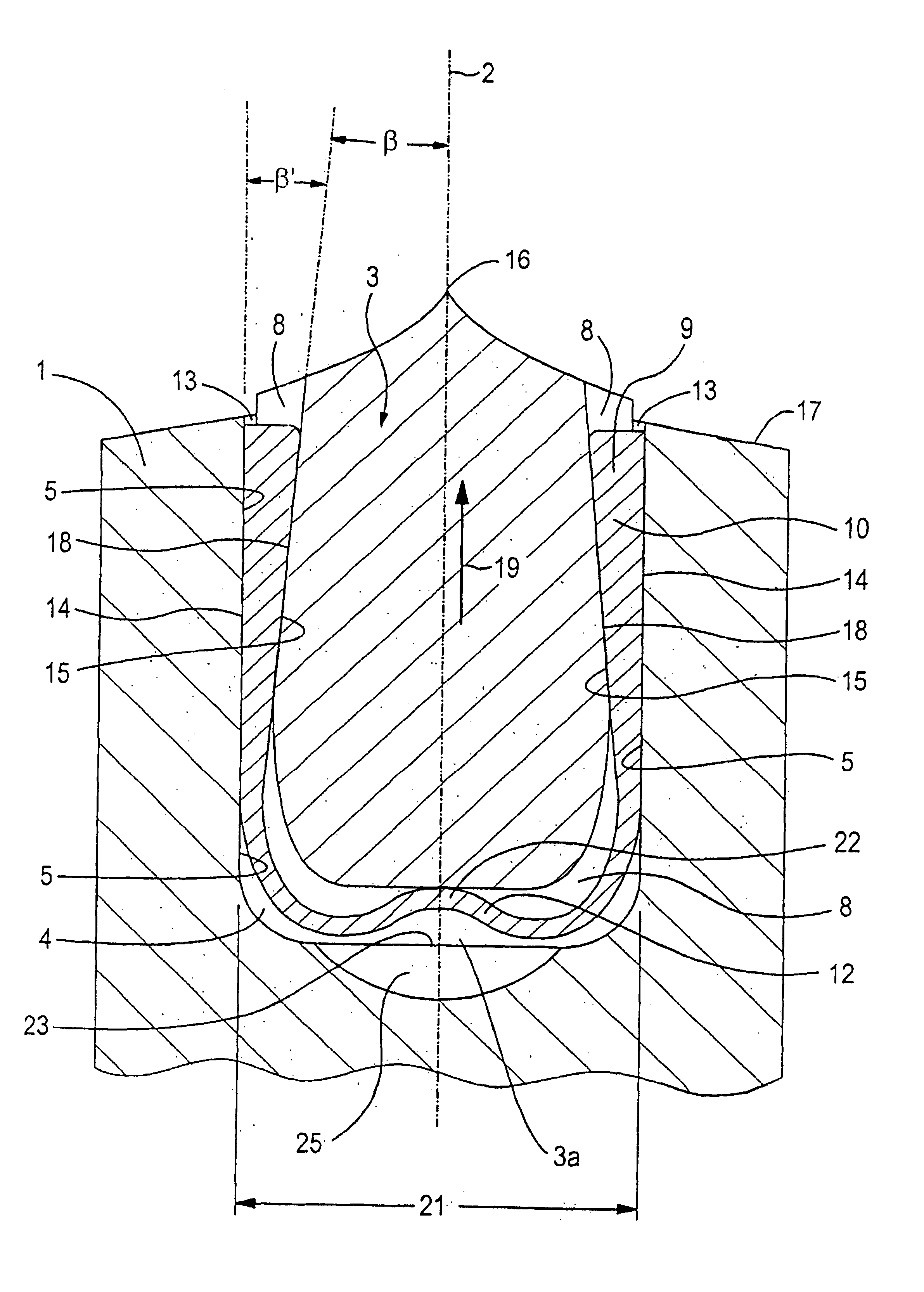
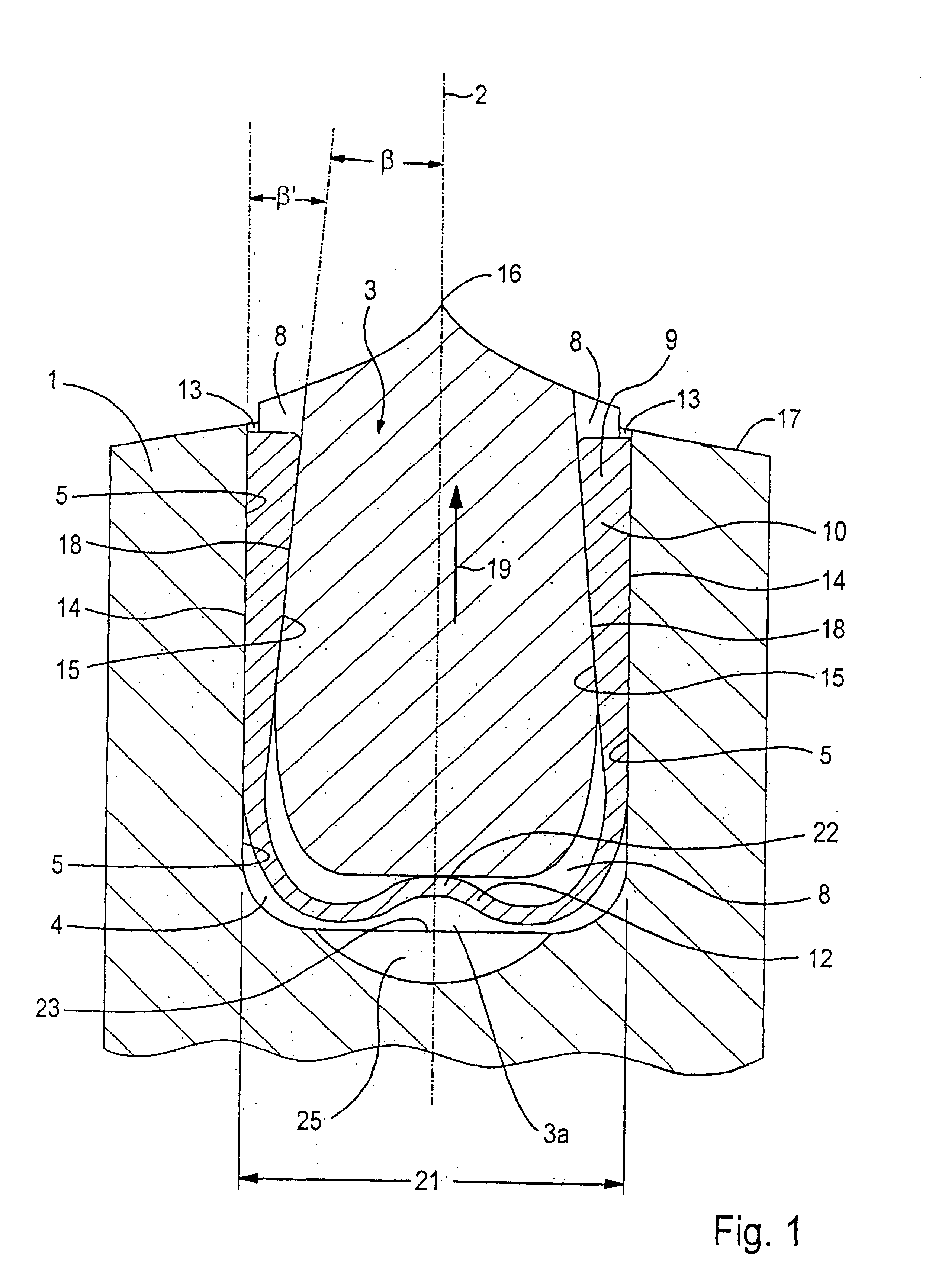
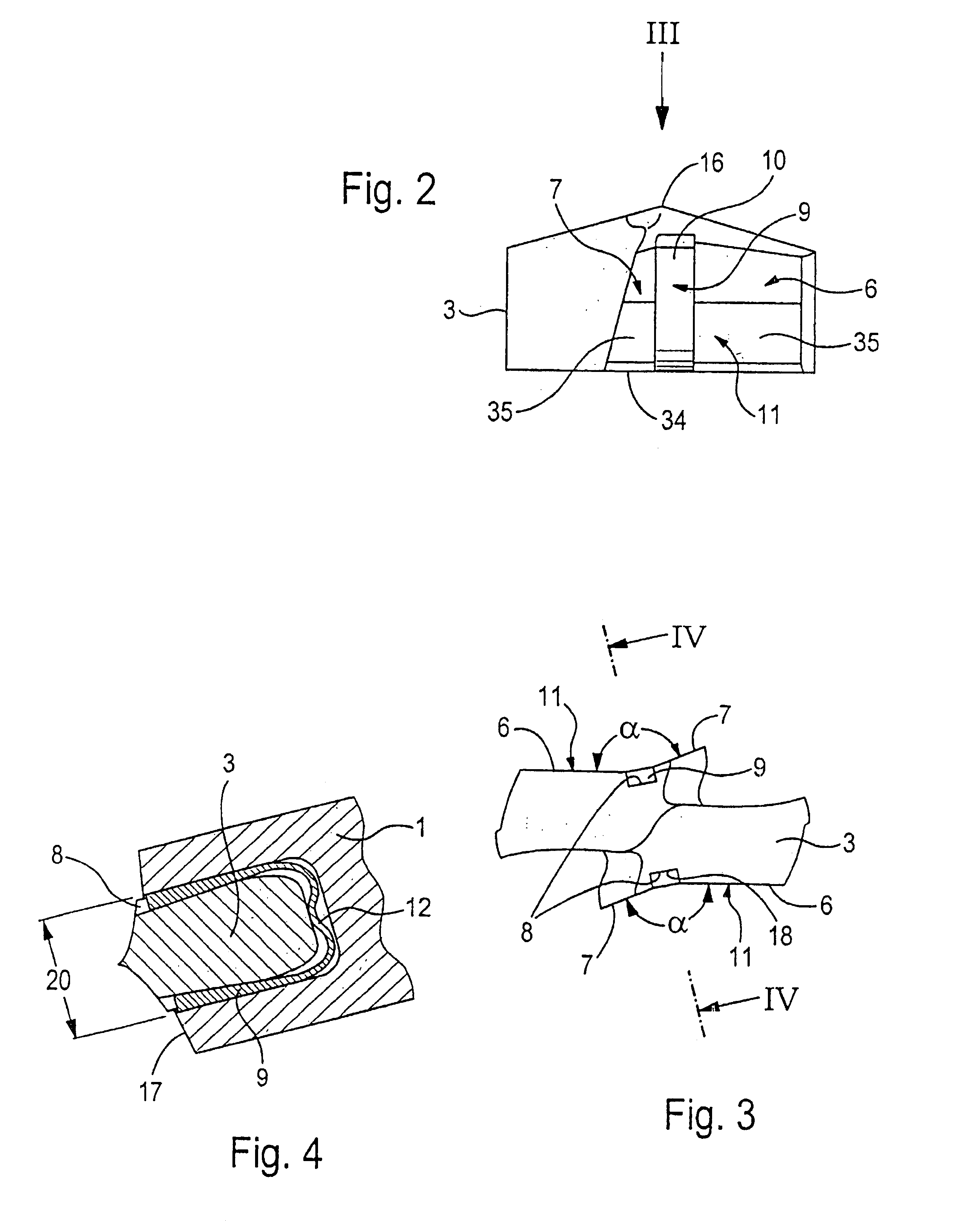
[0034]The drill illustrated in FIG. 1 has a base body 1 and a receptacle 4 which carries a cutting insert 3. The recess in the tip area of the base body 1 that forms the receptacle 4 becomes wider toward the end surface 17 of the base body 1 and extends through the base body at a right angle to the longitudinal axis 2 of the drill. As shown in the plan view in FIG. 3, the cutting insert 3 has lateral contact surfaces 11 that interact in a form-fitting manner with the side wall 5 of the receptacle 2. The contact surfaces 11 are composed of two prismatic surfaces 6, 7 that enclose an obtuse angle α. The prismatic surfaces 7—7 and 6—6 are arranged diametrically opposite each other in pairs and run parallel to each other. The side wall 5 of the receptacle 4 has a complementary configuration, so that the cutting insert is fixed in position in the base body by its form fit in the radial direction. At the point where the two prismatic surfaces 6, 7 contact one another, there is a groove 8 ...


PUM

PropertyMeasurementUnit
Angleaaaaaaaaaa
Angleaaaaaaaaaa
Elasticityaaaaaaaaaa

Abstract

On a drill with a base body and a replaceable cutting insert, the cutting insert lies in a receptacle that runs through the base body at a right angle to the latter's longitudinal axis and is open toward the drill tip, whereby the cutting insert is in contact by means of two diametrically opposite contact surfaces against the side walls of the receptacle. Between each contact surface of the cutting insert and a side wall of the receptacle, there is a groove that extends in the direction of the longitudinal axis, in which groove a clamping wedge sits with a form-fit and a friction-fit, and interacts with the base body and the cutting insert in the manner of a self-locking device that acts toward the drill tip.

Description

CONTINUING APPLICATION DATA[0001]This application is a Continuation-in-part of International Application No. PCT / EP00 / 02515, filed on Mar. 22, 2000, which claims priority from Federal Republic of Germany Patent Application No. 199 14 170.3, filed on Mar. 29, 1999. The United States was an elected state in International Application No. PCT / EP00 / 02515. International Application No. PCT / EP00 / 02515 was pending as of the filing date of this application.BACKGROUND OF THE INVENTION[0002]1. Field of the Invention[0003]This invention relates to a twist drill for drilling, a drill with a cutting insert, and a replaceable cutting insert for a twist drill.[0004]This invention also relates to a drill with a replaceable cutting insert, whereby the cutting insert sits in a receptacle that runs through the base body at a right angle to its longitudinal axis and opens toward the drill tip, and whereby the cutting insert is in contact with the side walls of the receptacle with two essentially diametr...

Claims


Application Information

Patent Timeline
IPC IPC(8): B23B51/02B23B51/00
CPCB23B51/02B23B2251/02B23B2251/50Y10T408/9098Y10T408/9097Y10T408/78Y10T408/907Y10S408/713
Inventor KRENZER, ULRICH
Owner KENNAMETAL INC
Why Eureka
Try Eureka