Electric refrigeration compressor having a cooling system for an electrical circuit

Inactive Publication Date: 2006-03-07
DENSO CORP
View PDF21 Cites 55 Cited by
  • Summary
  • Abstract
  • Description
  • Claims
  • Application Information

AI Technical Summary

Benefits of technology

[0007]In view of the above-described problems, it is an object of the present i

Problems solved by technology

However, because the shapes of the casing and the motor housing are different from each other, an unused space or “dead space” is formed in the motor housing.
Thus, the electrical circuit disposed in the

Method used


Image

  • Electric refrigeration compressor having a cooling system for an electrical circuit
  • Electric refrigeration compressor having a cooling system for an electrical circuit
  • Electric refrigeration compressor having a cooling system for an electrical circuit

Examples


first embodiment

[First Embodiment]

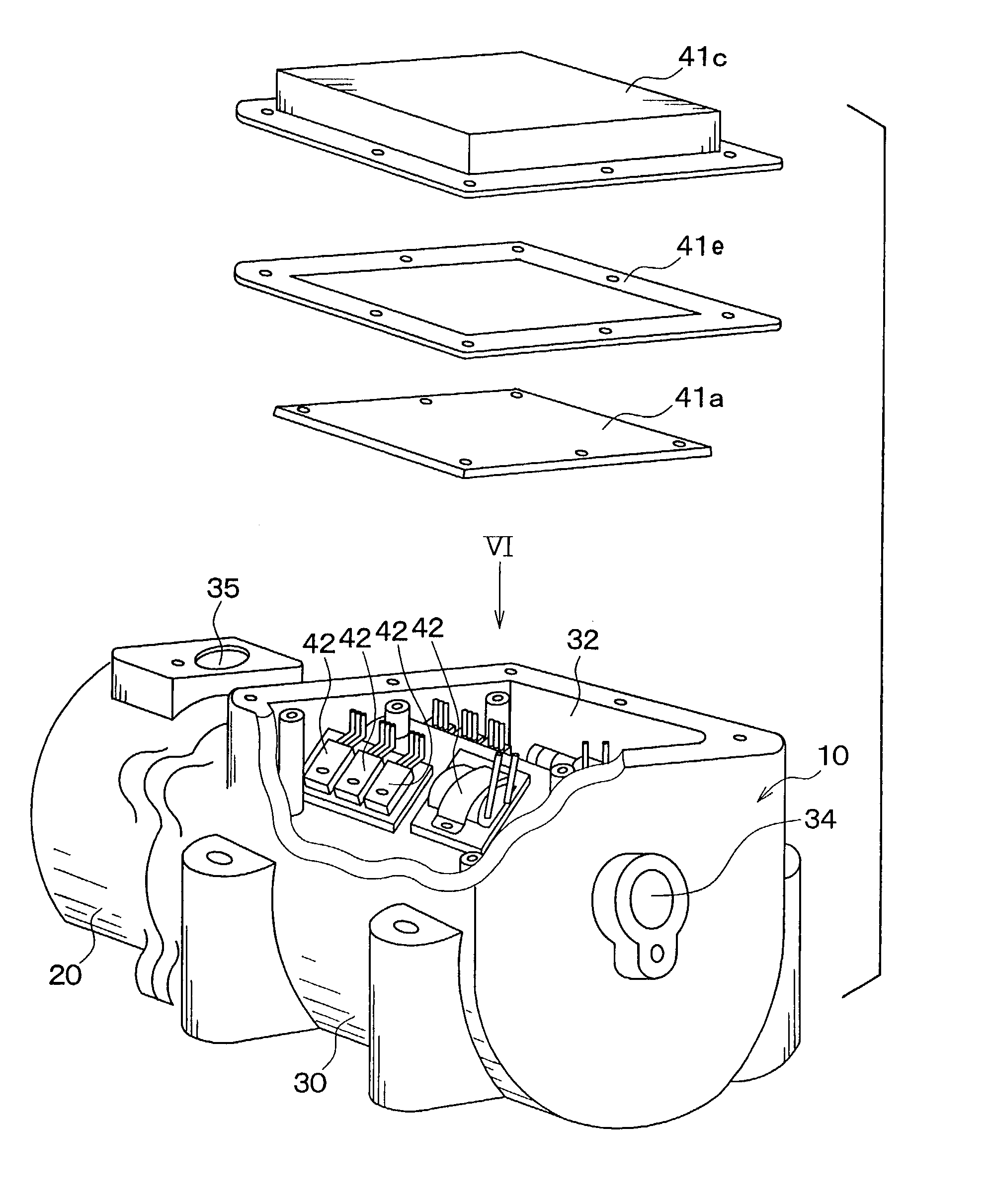
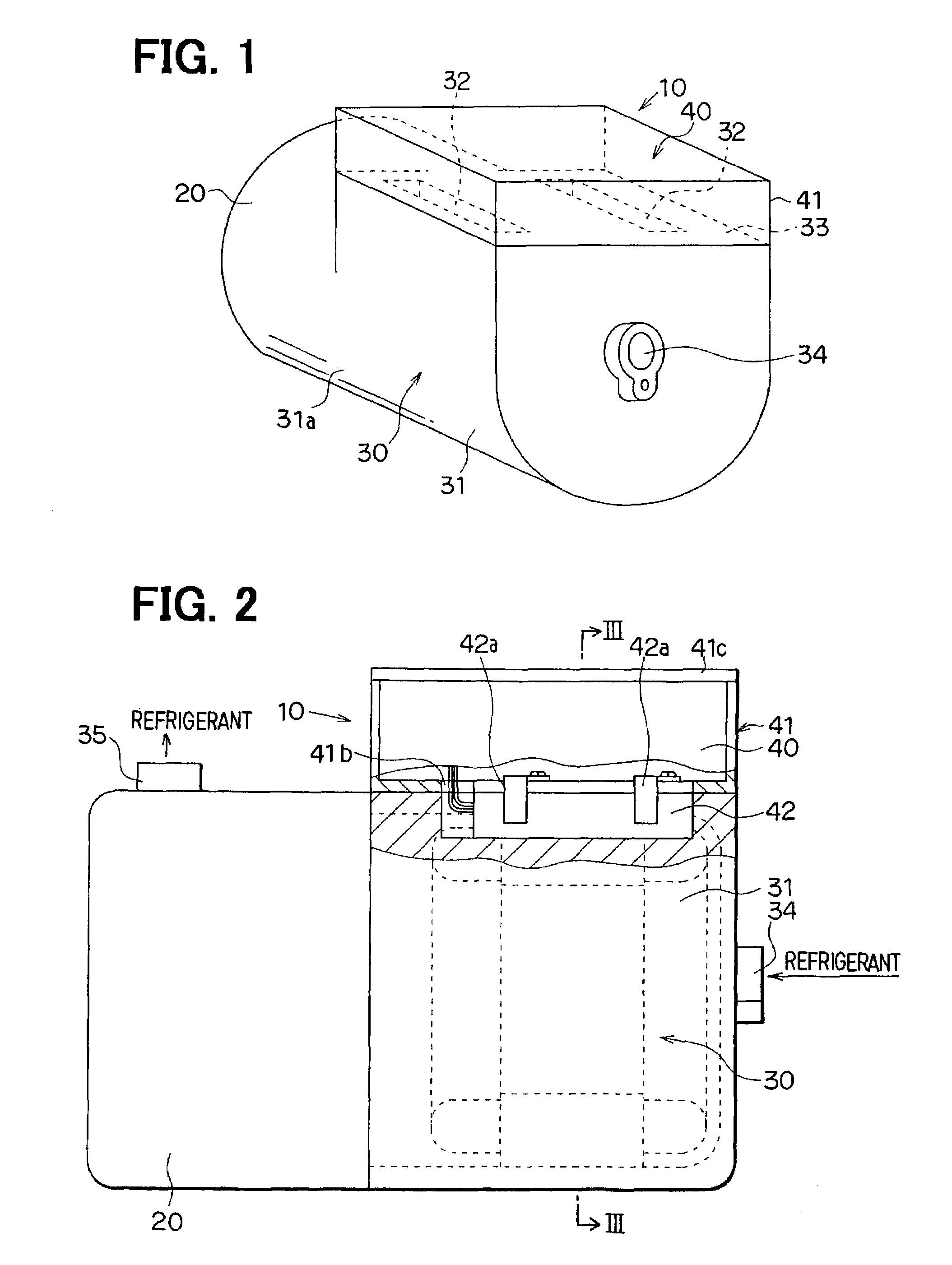
[0028]In this embodiment, the present invention is typically applied to an electrical compressor of a vapor-compression refrigerant cycle for a vehicle air conditioner. As shown in FIG. 1, an electrical compressor 10 includes a scroll type compression mechanism 20 (compression portion) for sucking and compressing refrigerant, a DC brushless electrical motor 30 for driving the compression mechanism 20, and an electrical circuit 40 composed of an inverter circuit for driving the motor 30. The compression mechanism 20 and the motor 30 are generally attached to the same shaft on the same line.

[0029]The compression mechanism 20 and the motor 30 are disposed in a motor housing 31 having an approximate cylindrical shape, and the electrical circuit 40 is disposed in a casing 41. The casing 41 is attached to a cylindrical outer surface 31a of the motor housing 31 by using a fastening member such as bolts, so that the electrical circuit 40 is integrated to the compression me...

second embodiment

[Second Embodiment]

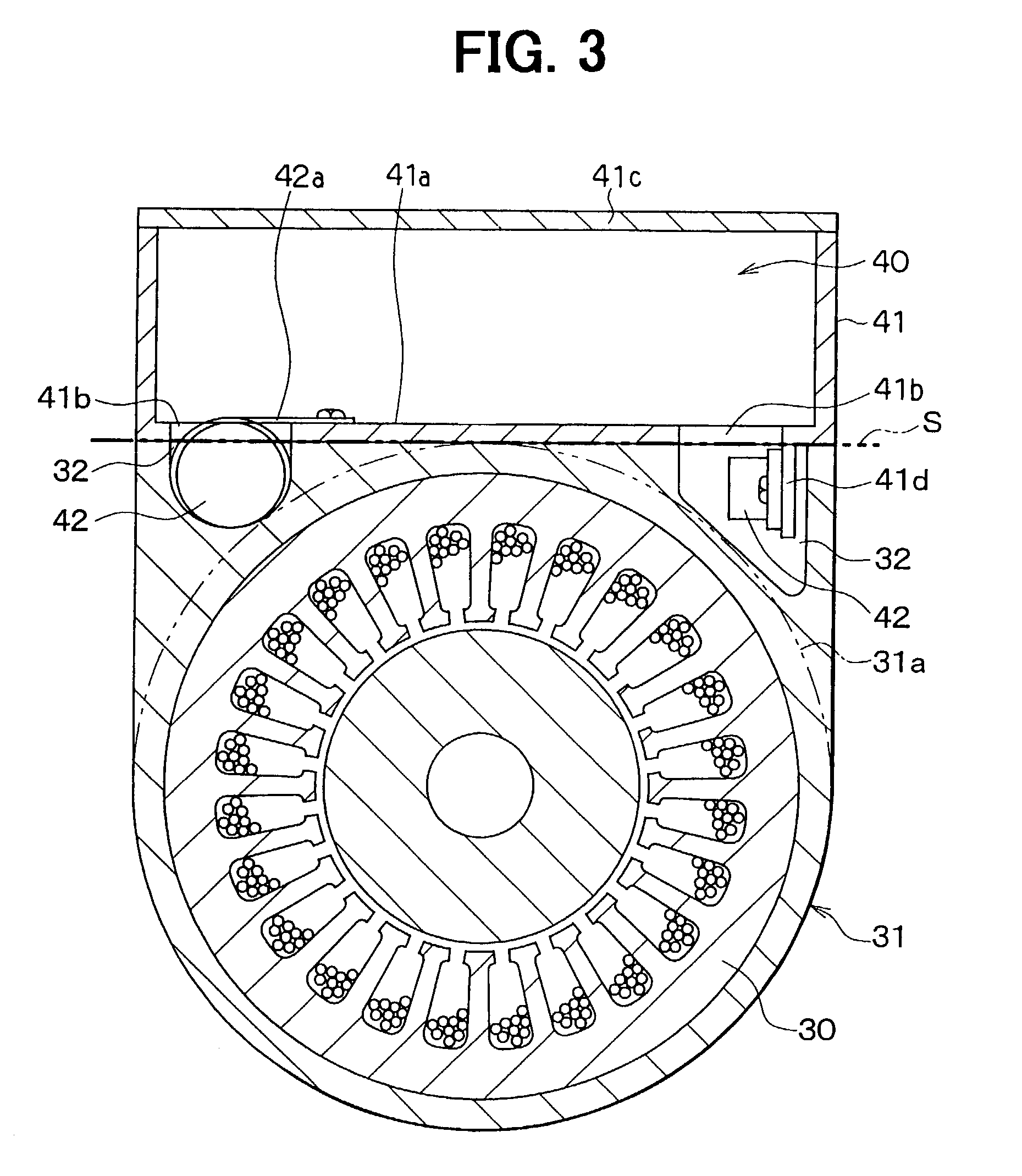
[0040]In the above-described first embodiment, the electrical parts 42 are fixed to the casing 41. However, in the second embodiment, as shown in FIGS. 5–8, the electrical parts 42 are disposed in the space 32 formed between the imaginary flat surface S and the cylindrical outer surface 31a, and the electrical parts 42 are fixed to the cylindrical outer surface 31a of the motor housing 31. Moreover, the positions of the cylindrical outer surface 31a, where the electrical parts 42 are fixed, are formed into a flat shape so that electrical parts 42 can be stably fixed to the cylindrical outer surface 31a. In the second embodiment, the insulating gel that has a high thermal conductivity is filled around the electrical parts 42, so that heat radiation performance of the electrical parts 42 is improved.

[0041]As shown in FIG. 5, in the second embodiment, the bottom plate 41a is used as a wiring board, and the casing cover 41c and the bottom plate 41a are fixed to the mo...

third embodiment

[Third Embodiment]

[0045]The third embodiment of the present invention will be now described with reference to FIGS. 10, 11A and 11B. FIG. 10 shows a vapor-compression refrigerant cycle in which an electrical compressor 100 of the third embodiment is typically used. The refrigerant cycle includes the electrical compressor 100 for compressing refrigerant, and a radiator 200 that cools the refrigerant discharged from the compressor 100. Refrigerant from the radiator 200 flows into a receiver 300 to be separated into gas refrigerant and liquid refrigerant in the receiver 200. Liquid refrigerant separated in the receiver 200 flows into an expansion valve 400 to be decompressed in the expansion valve 400. Low-pressure refrigerant decompressed in the expansion valve 400 flows into an evaporator 500, and is evaporated in the evaporator 500 by absorbing heat from air. Therefore, air passing through the evaporator 500 is cooled. In the third embodiment, the expansion valve 400 is used as a de...


PUM


Abstract

In an electrical compressor having a motor and an electrical circuit integrated with a compression portion, a part of electrical components of the electrical circuit is disposed in spaces between a cylindrical outer surface of a motor housing and an imaginary flat surface that imaginarily contacts the cylindrical outer surface. Therefore, the spaces can be used effectively, and the electrical compressor can be downsized. Further, the part of the electrical components can be effectively cooled by refrigerant in the motor housing. On the other hand, the outer surface of the motor housing is used as one surface defining an inner space of a casing for accommodating the electrical circuit. In this case, the electrical circuit can be effectively cooled by refrigerant in the motor housing.

Description

CROSS REFERENCE TO RELATED APPLICATION[0001]This application is based on and incorporates herein by reference Japanese Patent Applications No. 2002-21545 filed on Jan. 30, 2002 and No. 2002-62398 filed on Mar. 7, 2002.[0002]1. Filed of the Invention[0003]The present invention relates to an electrical compressor including a compression portion, a motor and an electrical circuit for driving the motor, which are disposed integrally. The electrical compressor can be suitably used for a vapor-compression refrigerant cycle.[0004]2. Background of the Invention[0005]In an electrical compressor, a compression portion, a motor, and an electrical circuit for the motor are integrated. In the integrated electrical compressor, a casing for accommodating the electrical circuit and a motor housing are integrated. However, because the shapes of the casing and the motor housing are different from each other, an unused space or “dead space” is formed in the motor housing. Therefore, the thickness of t...

Claims


Application Information

Patent Timeline
IPC IPC(8): H02K9/00F04B35/04F04B39/06F04C23/00F04C29/04H02K11/04
CPCF04B35/04F04B39/06H02K11/0073F04C29/047F04C23/008F04C18/0215F04C2240/808H02K11/33
Inventor IRITANI, KUNIOKAWATA, HIROYUKIFUNAHASHI, KENJITAKEO, YUJISHINDO, YUSUKETAKEMOTO, TSUYOSHI
Owner DENSO CORP
Why Eureka
Try Eureka