Generating multi-phase clock signals using hierarchical delays
a hierarchical delay and clock signal technology, applied in pulse manipulation, pulse technique, instruments, etc., can solve the problems of less portability of various process technologies and difficult mass production of analog designs , the problem of difficult to mass produce reliably within stated specifications
- Summary
- Abstract
- Description
- Claims
- Application Information
AI Technical Summary
Benefits of technology
Problems solved by technology
Method used
Image
Examples
Embodiment Construction
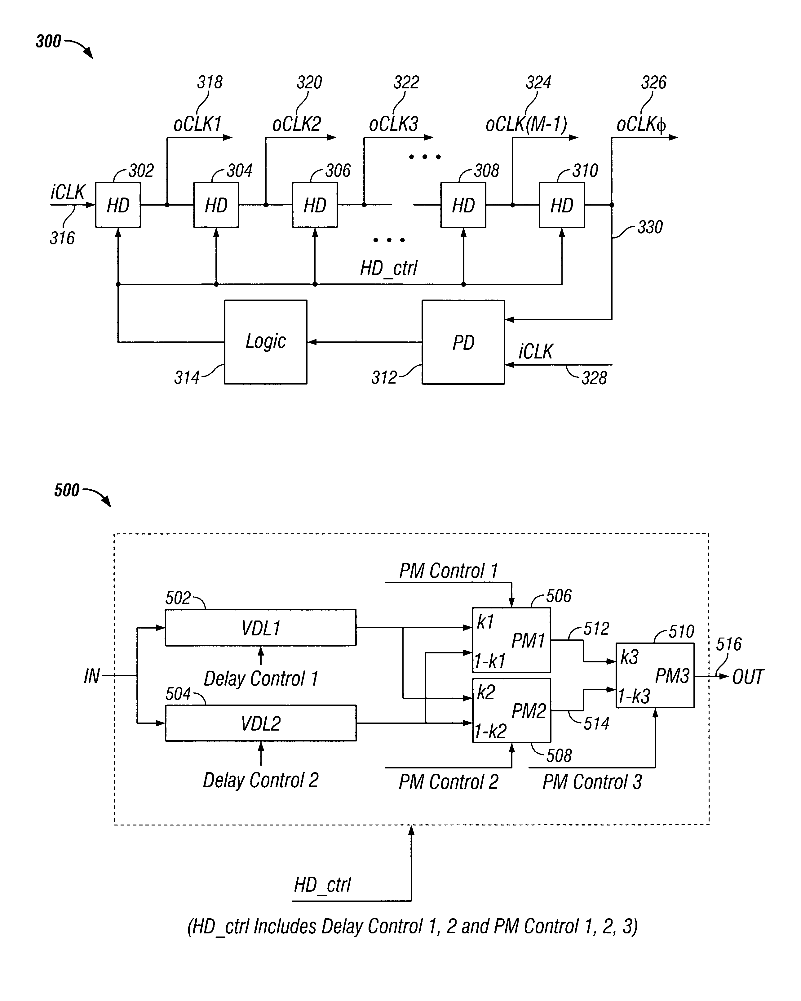
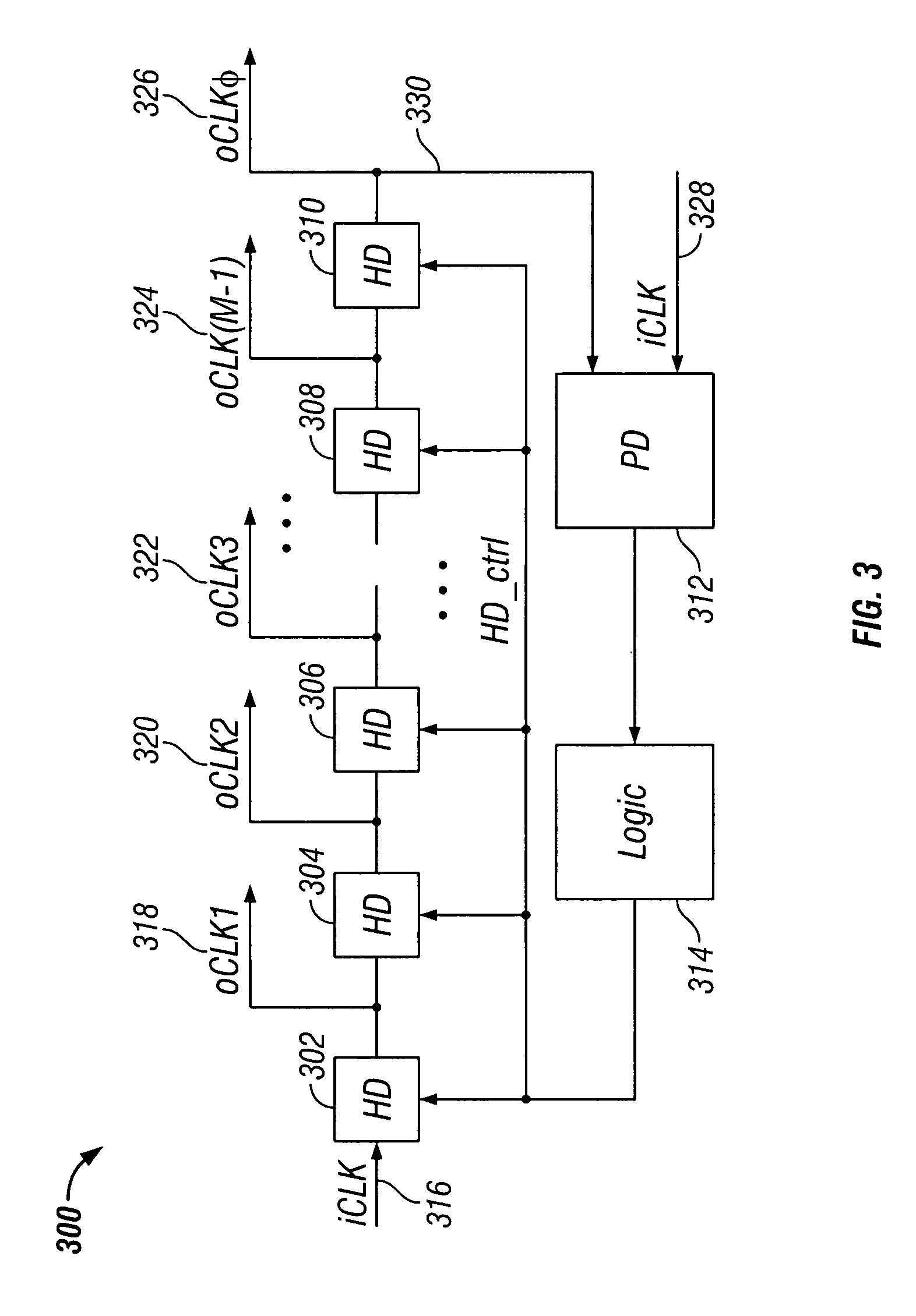
[0014]The invention relates to circuits and methods for generating multi-phase clock signals using hierarchical delay units, eliminating the need for analog VCDs, charge pumps and loop filters.
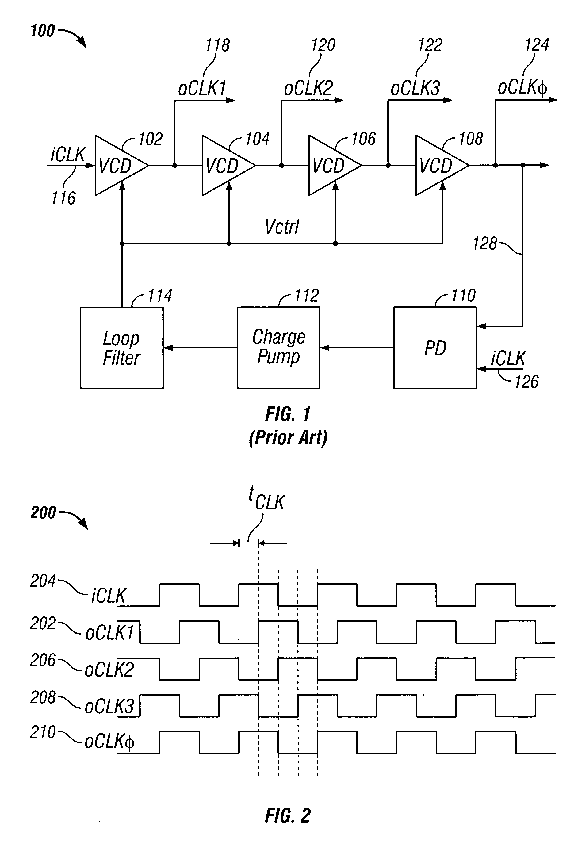
[0015]FIG. 1 shows a conventional circuit 100 for generating multi-phase clock signals. Circuit 100 includes a plurality of serially-coupled voltage-controlled delay units (VCDs) 102, 104, 106 and 108, phase detector 110, charge pump 112 and loop filter 114. A reference clock signal is input to VCD 102 (i.e., the first VCD in the serially-coupled chain) at input 116. In “locked” mode of operation, each VCD phase shifts (i.e., time delays) the reference clock signal by about (360 / M)°, where M is the total number of VCDs in the serially-coupled chain. VCDs 102, 104, 106 and 108 preferably do not change the frequency of the reference clock signal. In this example, circuit 100 has four VCDs 102, 104, 106 and 108 (i.e., M=4), and each VCD produces a phase shift of about (360 / 4)°=90°. “Locked” mode ...
PUM
 Abstract
Description
Claims
Application Information
 - R&D
- Intellectual Property
- Life Sciences
- Materials
- Tech Scout
- Unparalleled Data Quality
- Higher Quality Content
- 60% Fewer Hallucinations
Browse by: Latest US Patents, China's latest patents, Technical Efficacy Thesaurus, Application Domain, Technology Topic, Popular Technical Reports.
© 2025 PatSnap. All rights reserved.Legal|Privacy policy|Modern Slavery Act Transparency Statement|Sitemap|About US| Contact US: help@patsnap.com


