Stuck-at fault scan chain diagnostic method

a fault scan and diagnostic method technology, applied in the direction of instruments, coding, code conversion, etc., can solve the problems of lssd test methodology, critical rapid determination of fault root cause, and greatly reduced access to circuit internal logi

Inactive Publication Date: 2006-03-07
IBM CORP
View PDF1 Cites 33 Cited by
  • Summary
  • Abstract
  • Description
  • Claims
  • Application Information

AI Technical Summary

Problems solved by technology

A major drawback of LSSD test methodology is encountered when the LSSD scan chain circuit 104 is not functioning properly and access to the internal logic of the circuit is greatly reduced.
In these situations, the rapid determination of the fault's root cause is critical, but not easily diagnosed.
While several techniques have been developed in the past to diagnose this type of failure, these techniques have produced limited success in identifying the stuck-at fault location.
The suggested new latch / scan chain configurations generally add hardware overhead or offer minimum or no improvement in fault coverage.
Such software solutions for diagnosing the broken scan chain generally need more storage and simulation time, and if the logic circuits between the SRLs have faults, diagnostic resolution is very poor.

Method used


Image

  • Stuck-at fault scan chain diagnostic method
  • Stuck-at fault scan chain diagnostic method
  • Stuck-at fault scan chain diagnostic method

Examples


Embodiment Construction

[0017]Reference will now be made to embodiments of the invention shown in the accompanying drawings. Where possible, the same reference numerals are used throughout the drawings to refer to the same or like parts.

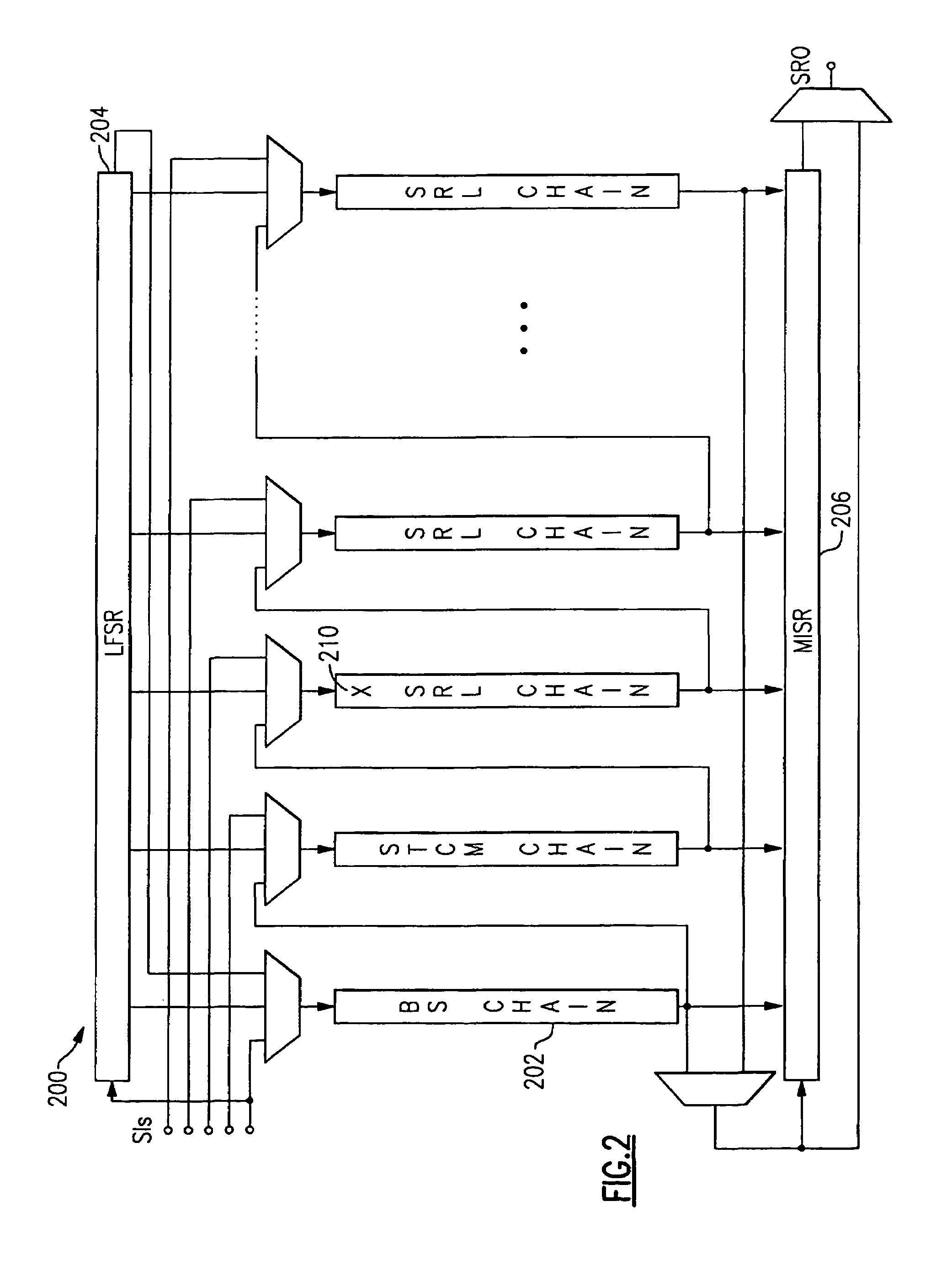
[0018]FIG. 2 shows a typical configuration for a LBIST circuit 200, shown in U.S. Pat. No. 5,983,380, the contents of which patent is hereby incorporated by reference. In that LBIST circuit, SRLs in the SRL chain 202 (with serial inputs (SIs) and serial output (SRO)) perform both input data launching and output data capturing. The test patterns come from a scan path that is configured into a linear feedback shift register (LFSR) 204. The test data are then outputted into the multiple input shift register (MISR) 206 for data compression. Alternate scan path shift cycles are applied to the SRLs exercising the combinational logic with the contents of the SRLs and capturing the results of the response of the combinational logic back into the SRLs where they are used as the test...


PUM


Abstract

While data cannot be transmitted down a scan chain through a stuck-at fault location, data in properly operating latches downstream of the stuck-at fault location can be shifted down the chain. By varying operating parameters, such as power supply and reference voltages, clock timing patterns, temperature and timing sequences, one or more latches down the SRL chain from the stuck-at fault location may be triggered to change state from the stuck-at fault value. The SRL chain is then operated to shift data out the output of the SRL chain. The output is monitored and any change in value from the stuck-at state is noted as identifying all good latch positions to end of the chain. The process is repeated: varying each of the selected operating parameters until the latch position following the stuck-at fault latch is identified.

Description

FIELD OF THE INVENTION[0001]The present invention relates to testing of complex combinatorial and sequential logic circuits embodied in large scale integration (LSI) and very large scale integration (VLSI) circuit devices and more particularly, to the diagnosing of broken or stuck-at fault scan chains.BACKGROUND OF THE INVENTION[0002]A fault occurring anywhere in such a LSI or VLSI circuit device can have its effect propagated through a number of feedback loops including storage or memory elements in the sequential logic before reaching a testable output of the device. Level sensitive scan design (LSSD) rules were devised to eliminate the complications in testing caused by this propagation through feedback loops. As described by E. B. Eichelberger and T. W. Williams in an article entitled “A Logic Design Structure for LSI Testablility” on pages 462–468 of the Proceedings of the 14th Design Automation conf., LSSD rules impose a clocked structure on logic circuit memory elements such ...

Claims


Application Information

Patent Timeline
Patent Type & Authority Patents(United States)
IPC IPC(8): G01R31/28G01R31/3183G11C29/02G11C29/32
CPCG01R31/318342G11C29/32G11C29/025G11C29/02
Inventor MOTIKA, FRANCONIGH, PHILIP J.SONG, PEILIN
Owner IBM CORP
Why Eureka
Try Eureka