
Composite polymeric twist tie

Inactive Publication Date: 2006-03-14
BEDFORD IND INC
View PDF11 Cites 53 Cited by
  • Summary
  • Abstract
  • Description
  • Claims
  • Application Information

AI Technical Summary

Benefits of technology

[0011]It will be understood that the instant invention utilizes the same oriented thermoplastic monofilament having an oriented characteristic produced by stretching the monofilament through a volume reducing die that was heated to a controlled temperature, as taught in the joint inventor's previous patent discussed above. It was found that the twist tie manufactured in accordance with U.S. Pat. No. 6,372,068 and application Ser. No. 10 / 095,765 functioned properly however an improvement has been found that not only produces complete uniformity and consistency in the manufacturing process but is much simpler and less costly to fabricate.
[0012]A patentably significant change was made in the twist tie which utilizes the successful oriented thermoplastic monofilament in conjunction with an extruded coating, which includes an integral pair of wings. This improvement eliminates the step of bonding the monofilament to a separate substrate using an ultrasonic weld and combines the two separate elements with connecting means into a single step of extruding a coating over the oriented monofilament which simultaneously forms the wings. This improvement now makes the twist tie even more practical.
[0013]Preferably the invention utilizes two elements made of dissimilar thermoplastic material, a monofilament made of a substance that has the properties of malleable metal wire, in that it is and stays bent to a useable extent, and twists out of the way without breaking and a coating with pair of wings protruding on each side. The tie also preferably substantially reverts to its normal body shape when it is untwisted. Use of these preferred thermoplastic materials in the manufacture of the twist tie permit the monofilament to be twisted and retain this union with the wings that are included in the coating; allowing the wings to follow the monofilaments orientation easily without cracking or yielding.
[0015]Yet another object of the invention is that the equipment necessary for orienting the monofilament, while specially fabricated, may be readily available as well as the preferred extruding apparatus well known in the art thus allowing the finished product to be competitively priced creating an advantage to the public.

Problems solved by technology

In the food industry where their use is widespread, typically bread bags, and other polyethylene bags for various edible products, the ties are mechanically attached and have die cut sharp ends that may inadvertently puncture the bag itself exposing the product to the atmosphere or even piercing the user's fingers or hands.
This automatic procedure makes the use of a wire embedded tie extremely objectionable at best and may even eliminate the possibility of its use entirely.
Also since a conventional tie utilizes metal in its composition the original product package employing this type of tie may not be heated in a microwave oven (as high frequency radiation arcs when metal is present) therefore necessitating additional and unnecessary handling and preparation of the packaged product by the user.
Another disadvantage to the use of metal in the tie material is that where the ends of the wire that have been cut off or the plating has been worn off by repeated twisting this surface may introduce undesired oxidization in the form of rust in the presence of moisture.

Method used


Image

  • Composite polymeric twist tie
  • Composite polymeric twist tie
  • Composite polymeric twist tie

Examples


Embodiment Construction

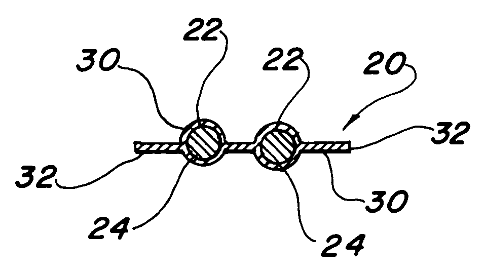
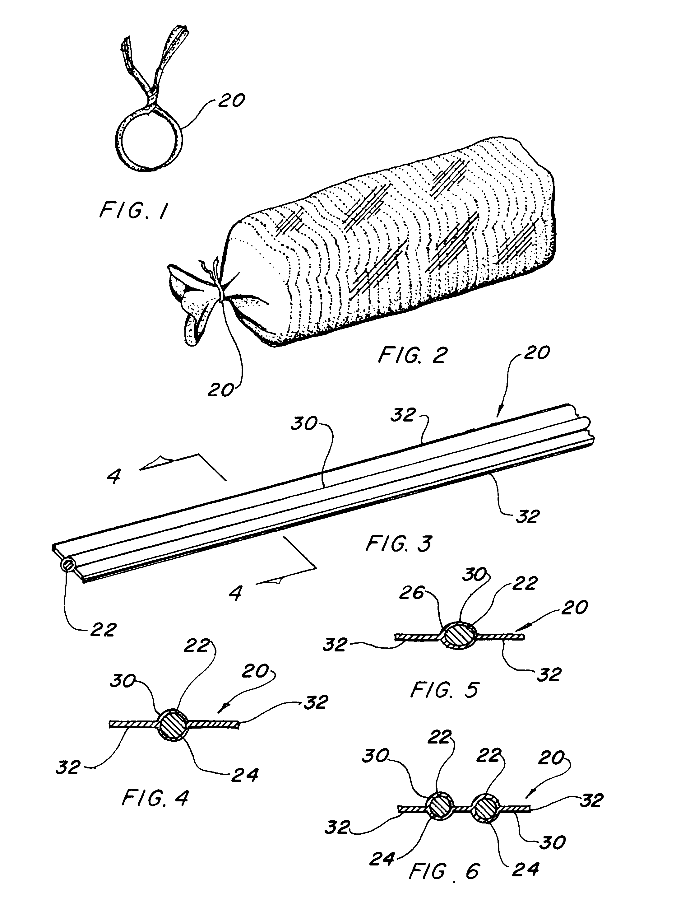
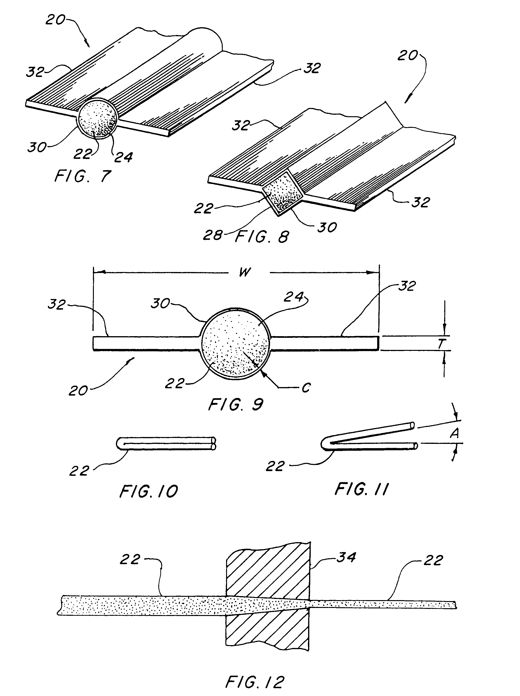
[0029]The best mode for carrying out the invention is presented in terms of a preferred embodiment. This preferred embodiment is shown in FIGS. 1 through 11 and is comprised of a composite polymeric twist tie 20 that is preferably formed using an oriented thermoplastic monofilament 22 having an oriented characteristic produced by stretching the preheated monofilament through a heated volume reducing die. Any other suitable method of manufacture can be utilized.

[0030]The oriented thermoplastic monofilament 22 preferably has a round shape 24 with a diameter of from 0.022 to 0.042 inches (0.056 to 0.107 cm) as shown in FIGS. 4, 6, 7 and 9. While this shape is basically conventional, since the prior art wire core it is replacing is round, it is not limited to this configuration as it may be formed with a substantially oval shape 26, as shown in FIG. 5, a substantially square shape 28 illustrated in FIG. 8 or any other external shape and still be within the parameters of this invention. ...


PUM

PropertyMeasurementUnit
Thicknessaaaaaaaaaa
Thicknessaaaaaaaaaa
Pressureaaaaaaaaaa

Abstract

A polymeric twist tie 20 is taught that utilizes a thermoplastic monofilament 22 having an oriented characteristic produced by stretching a pre-heated monofilament through a heated, volume reducing die. The monofilament 22 is then coated 30 circumferentially with an extrusion of thermoplastic enclosing the monofilament while simultaneously forming a pair of opposed wings 32 integral with the coating. The wings extend outwardly from the coated monofilament allowing the tie to be twisted upon itself with the monofilament retaining its basic configuration and the wings stretching and bending to conform within a coupled twist. The oriented monofilament is fabricated using high density polyethylene and the covering extruded with low density polyethylene which are dissimilar in density, melt index and basic thermoplastic morphology.

Description

CROSS REFERENCE TO RELATED APPLICATION[0001]This application is a continuation-in part of application Ser. No. 10 / 095,765 filed Mar. 13, 2002 now U.S. Pat. No. 6,673,413, which is a divisional application of application Ser. No. 09 / 583,021, filed May 30, 2000 now U.S. Pat. No. 6,372,068, which is a continuation-in-part of application Ser. No. 09 / 400,254, filed on Sep. 21, 1999, now abandoned.TECHNICAL FIELD[0002]The present invention relates to twist ties in general. More specifically to an entirely polymeric tie comprised of at least one thermoplastic monofilament that is coated with a dissimilar thermoplastic which is formed with integral outwardly extending wings.BACKGROUND ART[0003]Previously, many types of twist ties have been used in endeavoring to provide an effective means for closing or tying articles such as bags, fastening plants to stakes, securing bundled electric cable and other restraining tasks. These ties have included strings, wires, adhesive tape, and ribbon sandw...

Claims


Application Information

Patent Timeline
IPC IPC(8): B32B3/06
CPCB65D33/30Y10T428/24479Y10T428/24008Y10T428/24777Y10T24/157Y10T428/24612Y10T428/31913
Inventor CONTRERAS, LUIS C.HOFFA, JACK L.PATEL, DILIP R.
Owner BEDFORD IND INC
Learn More