Multi-stage dynamic braking resistor network

a dynamic braking resistor and multi-stage technology, applied in the direction of motor/generator/converter stopper, dynamo-electric converter control, instruments, etc., can solve the problems of increasing the load of the braking resistor on the system bus, damage to the system, and the inability to switch back into the conventional braking resistor, etc., to achieve the effect of dissipating excessive energy

Inactive Publication Date: 2006-03-14
HONEYWELL INT INC
View PDF39 Cites 40 Cited by
  • Summary
  • Abstract
  • Description
  • Claims
  • Application Information

AI Technical Summary

Benefits of technology

[0011]It is therefore an object of the present invention to provide a multi-stage dynamic braking resistor network that dissipates excessive energy placed on a system bus through regenerative braking and a method thereof.

Problems solved by technology

Typically, braking resistors increase a load on a system bus, whereby an increased load on the system bus will absorb the excessive energy generated by a rotary actuator or an electric motor.
When the power source is not receptive to such regenerative energy, an overvoltage will occur and possible damage could happen to the system.
After removal from the system bus, these conventional braking resistors cannot be switched back into the system bus until they have cooled down sufficiently.
A single large resistor, however, lacks flexibility and imposes an additional burden on the power system during the time it is coupled therewith if less than the total dissipation is required to respond to the disturbance.
Another drawback of using a single resistor is the voltage ripple generated by switching the resistor on or off.
Since the resistor should be rated so as to absorb the excessive energy for a worst case scenario, when the resistor is switched on, the system bus voltage will drop significantly, and when it is switched off, the voltage will kick back causing voltage overshoot on the system bus.
This voltage fluctuation will impact the power quality and cause EMI (Electro-Magnetic Interference) problems in the system.
This dynamic braking grid resistor configuration, however, does not provide any means for selectively switching the resistor configuration depending on specific system requirements.

Method used


Image

  • Multi-stage dynamic braking resistor network
  • Multi-stage dynamic braking resistor network
  • Multi-stage dynamic braking resistor network

Examples


Embodiment Construction

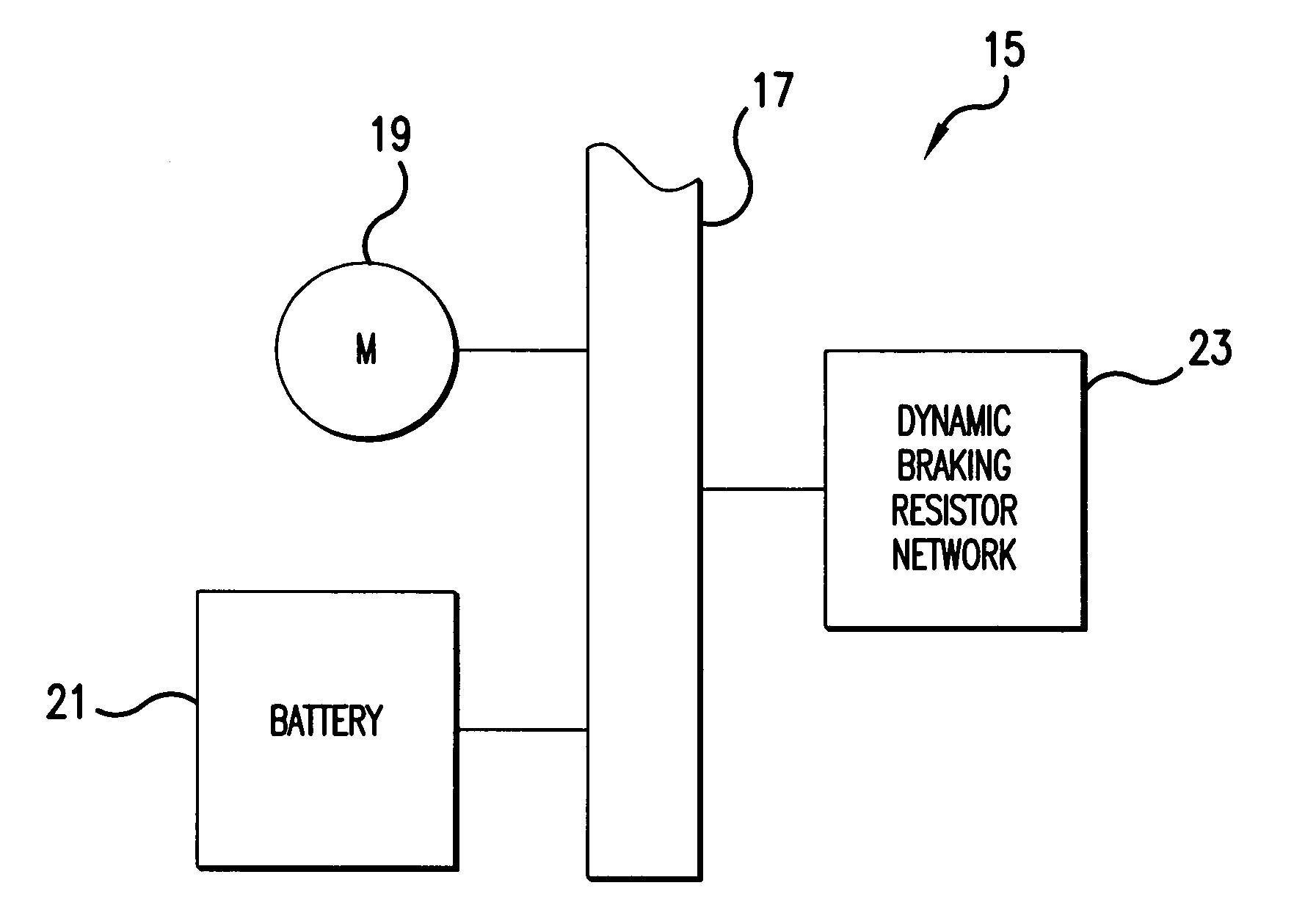
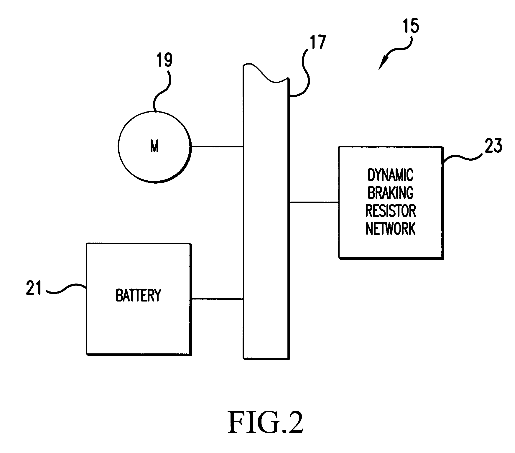
[0024]FIG. 2 is a block diagram showing a portion of a FCAS system 15. Although only one FCAS system 15 is shown, several FCAS systems can be connected to one another in, for example, an airplane, which may have eight FCAS systems. The FCAS system 15, shown in FIG. 2 includes, for example, a system bus 17, one or more motors or actuators 19, a battery 21, and a dynamic braking resistor network 23. Although it is not shown in FIG. 2, the dynamic braking resistor network 23 can include one or more dynamic brake resistors 1, which is discussed further below.

[0025]The dynamic braking resistor network 23 must be able to deal with a worst-case scenario of an FCAS system 15. A worst-case scenario is, for example, a simultaneous regeneration of all FCAS systems on one system bus 17. In other words, the dynamic braking resistor network 23 dissipates this regenerative energy, which is produced by the motors or actuators 19, without disturbing the battery voltage and maintains the battery volt...


PUM


Abstract

A multi-stage dynamic braking resistor network (23) is provided that includes a plurality of dynamic brake resistors (1a–d) for dissipating, as heat, regenerative energy inputted onto a system bus (17) by a motor or actuator (19), and a plurality of switches (31a–d) for connecting the dynamic brake resistors (1a–d) to and from the system bus (17), respectively. The multi-stage dynamic braking resistor network (23) further includes a control circuit (25) for controlling the switches (31a–d) such that the dynamic brake resistors (1a–d) are connected to and from the system bus (17) on the basis of a predetermined voltage threshold of the system bus and on the basis of a predetermined rotation pattern.

Description

BACKGROUND OF THE INVENTION[0001]1. Field of the Invention[0002]The present invention relates to a multi-stage dynamic braking resistor network and associated control circuitry for absorbing and dissipating energy that is put onto a system bus and a method thereof.[0003]2. Description of the Background Art[0004]Conventional braking impedances, which are typically referred to as braking resistors, have been applied to power systems, for example, remote generation locations. The braking resistor provides a shunt resistance path to ground when coupled with the power system via a switch.[0005]FIG. 1 is a perspective view of an example of a conventional dynamic brake resistor 2. The dynamic brake resistor 2 can be an assembly of grid elements, for example. Each assembly comprises a first stack 3 and a second stack 5, with each stack having an upper layer 7, 9 and a lower layer 11, 13. Each layer is formed, for example, from a plurality of stamped metal sheet units having a serpentine con...

Claims


Application Information

Patent Timeline
Patent Type & Authority Patents(United States)
IPC IPC(8): H02P3/14H02P3/22B60L7/22H02P3/06H02P3/12
CPCH02P3/12
Inventor NGUYEN, THATZHAO, QIHUA
Owner HONEYWELL INT INC
Why Eureka
Try Eureka