
Dimmer control system with two-way master-remote communication

a control system and remote control technology, applied in the direction of electric controllers, frequency-division multiplexes, instruments, etc., can solve the problems of imposing additional costs and difficulties in outfitting remote units with power sources and the capability, units that require no power in normal operation, and cannot display the light setting level

Active Publication Date: 2006-03-14
EATON INTELLIGENT POWER LTD
View PDF17 Cites 63 Cited by
  • Summary
  • Abstract
  • Description
  • Claims
  • Application Information

AI Technical Summary

Benefits of technology

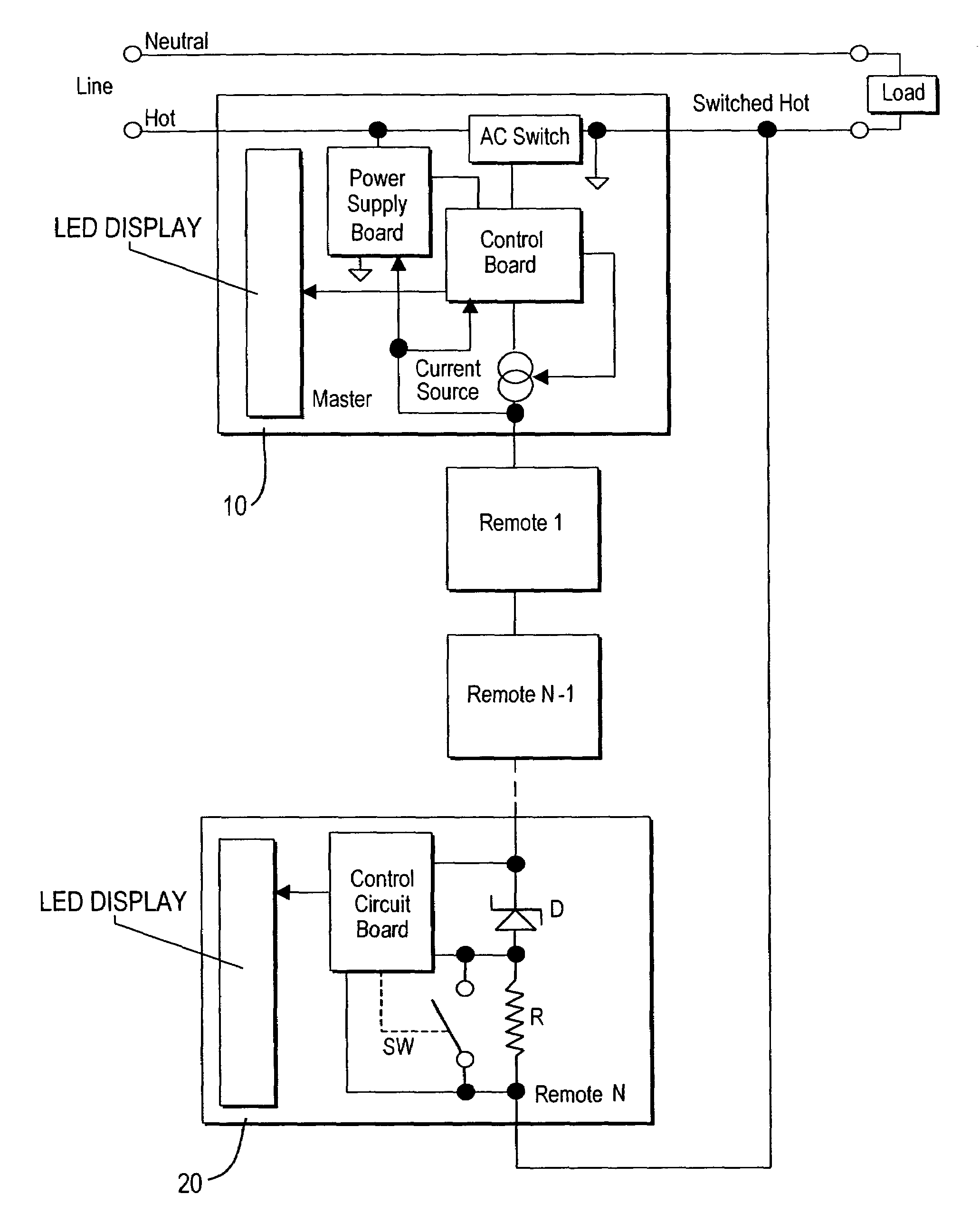
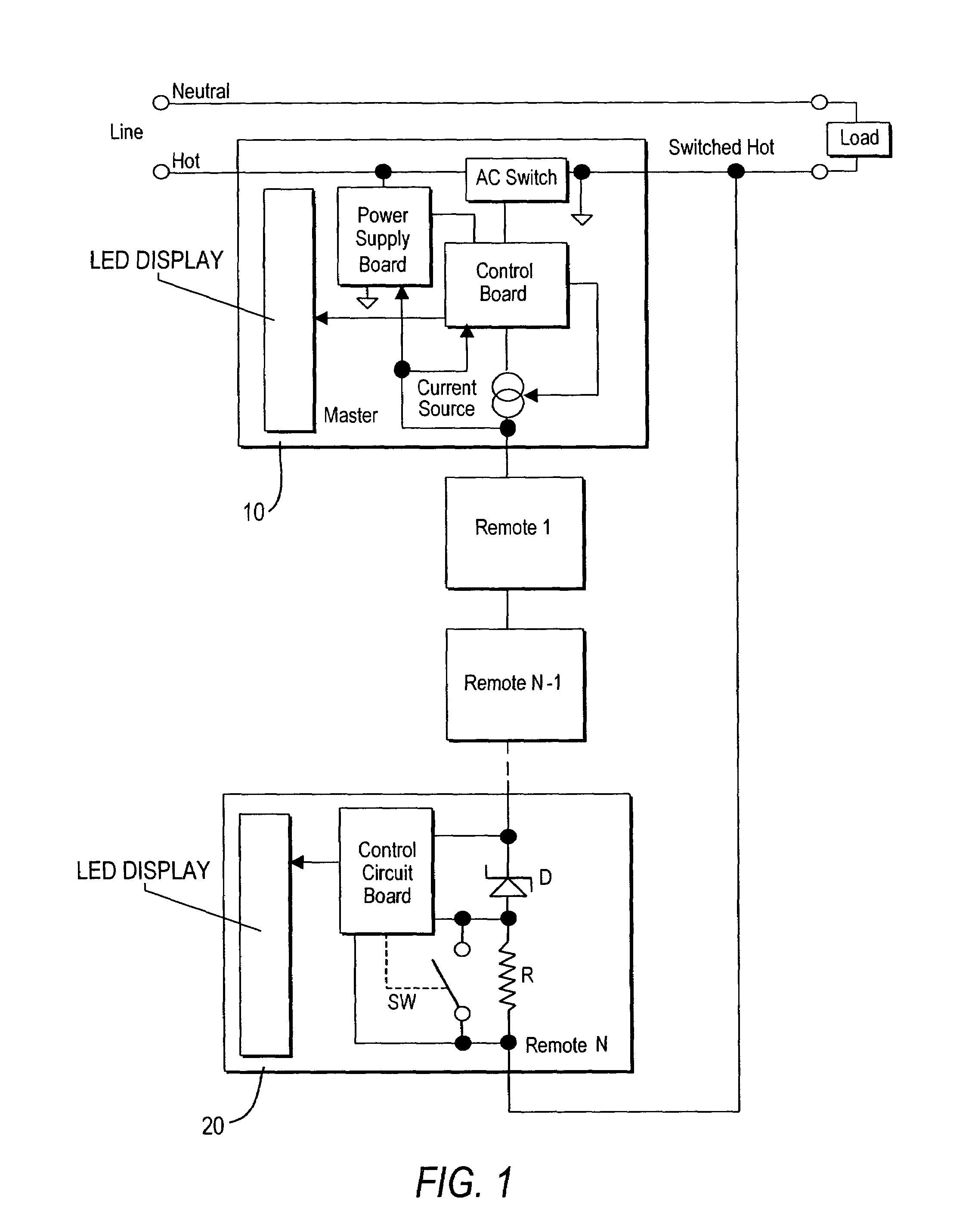
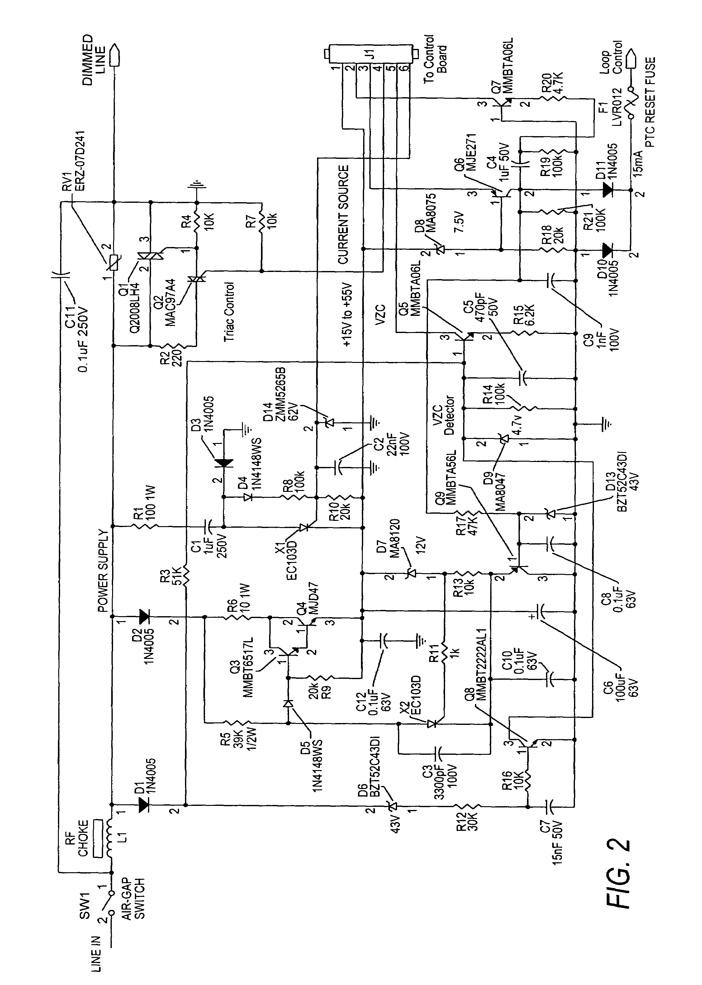
The present invention provides a dimmer control system with a communication control loop that allows two-way communication between a master unit and remote units without affecting the dimmer load current. The master unit uses a switched power supply and the communication loop is hosted and synchronized by the master unit. The master unit's power circuit maintains its switched power supply in tandem with a capacitive power supply to avoid acoustic noise in the load. The master unit's control circuit includes a non-volatile memory that is written with system status information when a POWER OFF condition is detected, and the system status information is used to restore the operation of the dimmer control system. The master and remote units have a physical configuration in which an ON / OFF switch component is hinged for slight actuator ON / OFF movement, and a system status display is formed by an array of light indicators that minimize light fluctuations in the display of the indicator lenses.

Problems solved by technology

However, prior multi-location dimmer control systems have various shortcomings and problems in operation.
Attempts to provide two-way communication functions between the master and remote units would impose added costs and difficulties in outfitting the remote units with power sources and the capability to communicate with the master unit.
These remote units require no power in normal operation, and cannot display the level of light setting.
The task of supplying power to the remote units is quite complicated, as every remote would need some current to operate.
For a multi-location dimmer that supplies power to the remote units, there may be a problem that the internal dimmer's power supply could create an audible noise in the load when the load is Off, which otherwise would be masked when the load is On.
This power supply may also generate waste heat.
However, the use of a separate latch device is limited to memorizing only whether the load was on or off, and the use of ongoing memory storage of the current power level requires use of a memory component capable of extremely high usage of read / write cycles, which imposes an added cost.

Method used


Image

  • Dimmer control system with two-way master-remote communication
  • Dimmer control system with two-way master-remote communication
  • Dimmer control system with two-way master-remote communication

Examples


Embodiment Construction

[0021]A preferred embodiment of the invention is herein described in detail, and is sometimes referred to as the “Smart Dimmer” system. It is to be understood that while a particular system configuration, circuit layouts, and modes of operation are described, other modifications and variations may be made thereto in accordance with the general principles of the invention disclosed herein.

[0022]The Smart Dimmer is a wall-mounted, electronic system for controlling the level of power delivered to a load, such as a light, lamp or fan, thereby also controlling the load's output (e.g., light intensity). The Smart Dimmer system may be installed with one “master unit” alone or in combination with one or more “remote units” each having a bottom housing for holding all of the electronic components and a cover including a frame portion on actuator switches for actuating the ON / OFF or dimming functions. Referring to FIG. 7A, a preferred design for the cover 70 of the master and remote units is ...


PUM


Abstract

A dimmer control system has a communication control loop that connects a master unit in series with a plurality of remote units, and it is superimposed in series on the dimmer load line so as to allow two-way communication between the master unit and remote units without affecting the operation of the load. Communications from the master to the remote units are encoded in loop current fluctuations, whereas communications from any remote to the master unit are encoded in loop voltage fluctuations. The master unit has a switched power supply, for use during normal LOAD ON operation, in tandem with a capacitive power supply, for use during LOAD OFF operation of the control units so as to minimize hum. The master unit power supply circuit provides an output rail voltage comprised of a reference voltage for the load superimposed with a control loop voltage for the voltage drop across the series-connected remote units. The master unit has a POWER OFF detection circuit and a non-volatile memory for storing system status information, so that when power is restored, the system can be restored to its former power level. The switch units are formed with a cover frame mounting a switch plate on a hinge axis allowing ON / OFF movement of an opposing side thereof. An array of LED light pipes is mounted in the switch plate aligned with the hinge axis, in order to minimize displacement of the light pipes during actuator movement.

Description

CROSS REFERENCE TO RELATED APPLICATIONS[0001]This application claims the benefit of U.S. Provisional Patent Application No. 60 / 463,845 filed Apr. 18, 2003, the disclosure of which is incorporated herein by reference.TECHNICAL FIELD[0002]This invention generally relates to a light dimmer control system, and more particularly, to a dimmer control system employing a master unit in communication with one or more remote units.BACKGROUND OF INVENTION[0003]Dimmer lighting and control systems are widely used in indoor lighting to provide a softer feel and more controllable illumination experience as compared to on / off lighting. Prior dimmer lighting systems have employed dimmer switch controls that include an on / off switch and an up / down power control, master unit and remote units, and microprocessor control for various power-up, power-down and fade in / out functions. Rather than use a variable resistor type rheostat which wastes power and generates heat at low illumination levels, modern di...

Claims


Application Information

Patent Timeline
Patent Type & Authority Patents(United States)
IPC IPC(8): G08B1/08H05B39/08
CPCH05B39/086H05B37/0263H02M5/257H05B47/185
Inventor NOVIKOV, LENNY M.
Owner EATON INTELLIGENT POWER LTD
Learn More