Method and device for determination of the wear resistance of a surface

a technology of wear resistance and surface, applied in the direction of measuring devices, scientific instruments, instruments, etc., can solve the problems of affecting the wear resistance of the surface, and changing the grinding characteristics of the surface, so as to achieve the effect of reliable determining the wear resistance of extremely thin surface installations and coatings, favorable cost, and quick

Inactive Publication Date: 2006-03-21
INNOWEP
View PDF28 Cites 23 Cited by
  • Summary
  • Abstract
  • Description
  • Claims
  • Application Information

AI Technical Summary

Benefits of technology

[0016]An object of the present invention is to provide a method and related apparatus for determining the mechanical wear resistance of a sample surface,

Problems solved by technology

The known micro-scratch tester based on the AFM method is not suitable for the determination of practically usable and transferable results since the scratch results, which are gained with the aid of a thin needle, permit no determination regarding the actual areal wear in practice.
It is disadvantageous that the polishing medium can cause a change its grinding characteristics, for example, by being soiled with abraded material, by deposit of particles and by evaporation losses of the fluid.
The polishing slurry can, furthermore, operate as a wear passive material when particles deposit in soft surfaces and it is unevenly spread over the counter-body's contact route.
Furthermore, this prior art method of load variation is limited by a reduction of the calotte radius.
Also, the pressure force of the ball can only be used restrictively.
When evaluating the measurement, failures of the calotte form

Method used


Image

  • Method and device for determination of the wear resistance of a surface
  • Method and device for determination of the wear resistance of a surface

Examples


Embodiment Construction

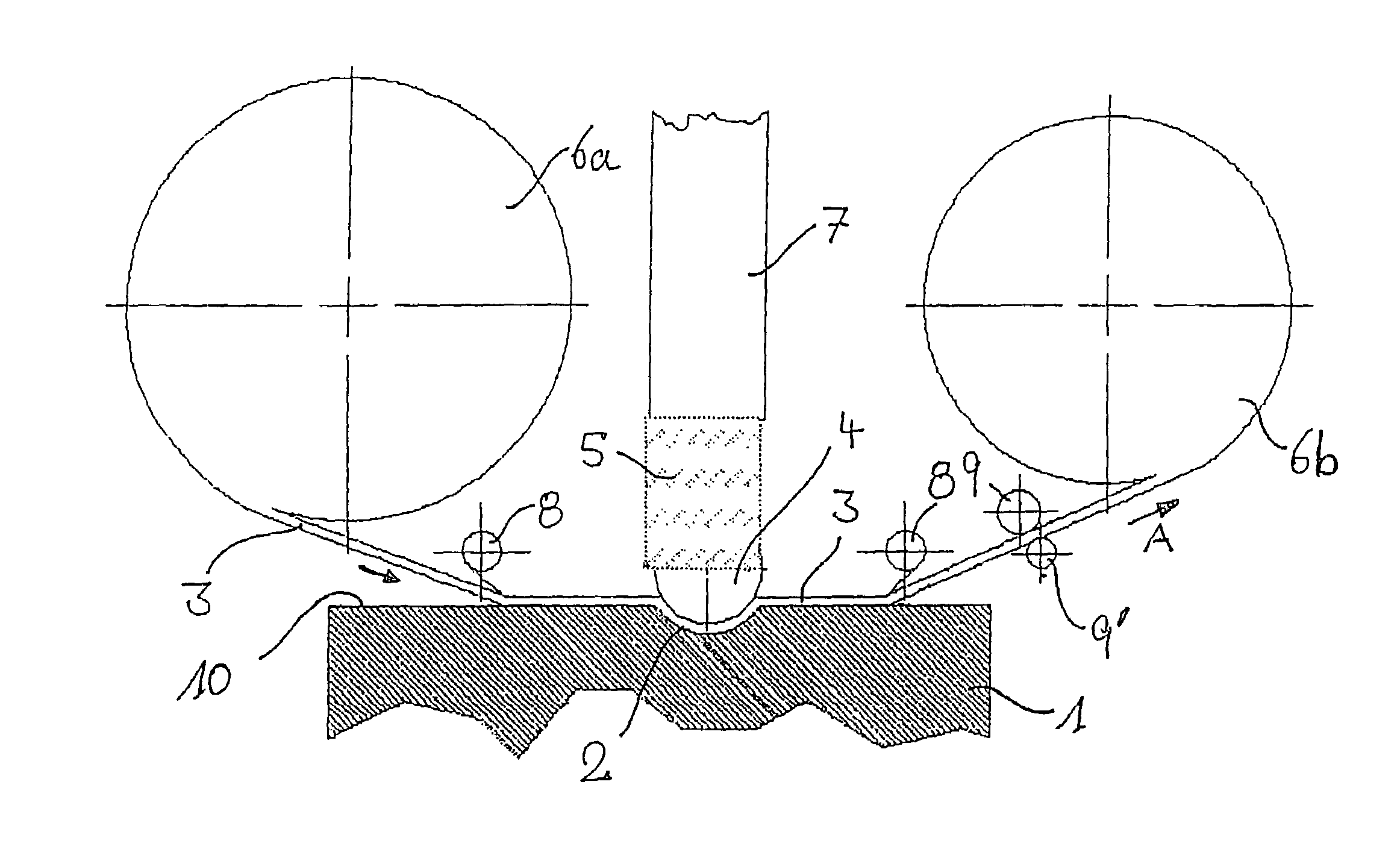
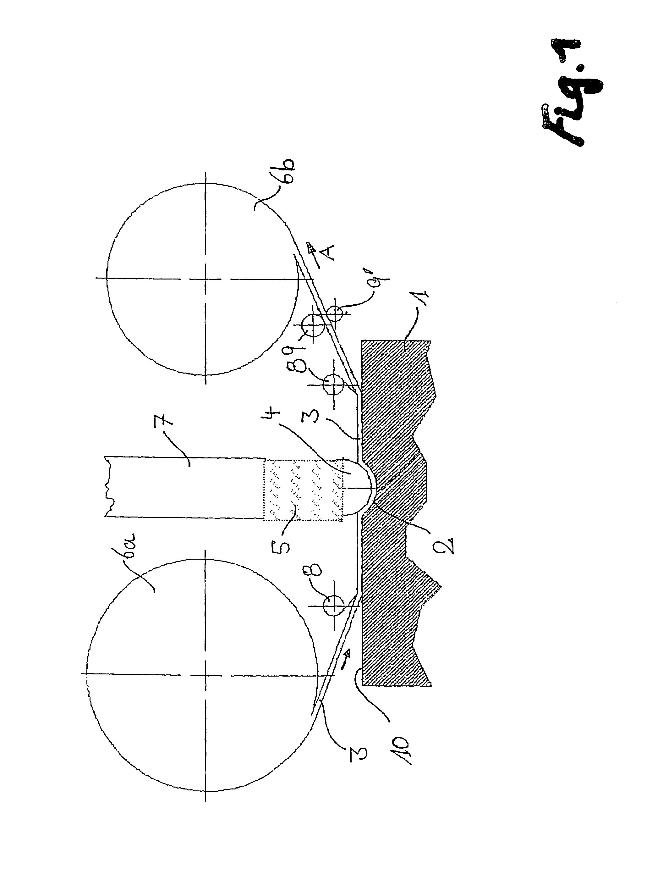
[0023]Since the determination of the position of the counter-body can be made, in situ, the tape thickness variation can be eliminated from the measurement by running back the belt into the same position at the respective measurement points of time. So the position of the counter-body is always able to be determined with the same tape thickness. The measurement of the counter-body's position can be made when the tape is stopped at one patch of the tape, which has not been used for generating wear. This has a particular importance, when calotte-depths are measured in a range of 10 nm, while the tape thickness is usually >10 micrometers (typically 10–20 micrometers) and up to a thousand times of the produced calotte-depth. This also enables the resolution of calotte-depths of a scale of 1 nm. Customary magnet tapes can be used as tapes, which enable the marking and of a certain tape position, so that the belt can be run back into the marked position for the single measurement points o...


PUM


Abstract

A method and apparatus for determining the wear resistance of the surface of a sample object includes an abrasive grinding belt, run between the sample object and a counter-body, with the grinding belt being pressed against the sample object with a predetermined force by the counter-body. The position of the counter-body is determined at, at least, a first position and a second position, each occurring at two different points in time. The wear resistance of the surface of the sample object is determined from the difference in determined positions.

Description

BACKGROUND OF THE INVENTION[0001]1. Field of the Invention[0002]The present invention relates to a method for determining the wear resistance of a material surface of a sample, utilizing a counter-body and a belt, with the belt being run between the sample and a counter-body, while the belt is pressed against the sample with a previously determined force, thereby allowing for the wear resistance of the sample surface to be determined.[0003]A related apparatus for determining the wear resistance of a material surface of a sample, comprising a counter-body and a belt is also taught, the apparatus being for holding and transport which holds and carries the belt over the sample surface. Further included is a counter-body holding device and a counter-body held by the counter-body holding device vertically movable, while the counter-body holding device is arranged so that the counter-body can be pressed on the side of the belt, which is turned away from the sample surface.[0004]The determ...

Claims


Application Information

Patent Timeline
IPC IPC(8): G01N19/02G01N3/00G01N3/02G01N3/06G01N3/56
CPCG01N3/56G01N19/02G01N2203/0682G01N2203/0282G01N2203/0082
Inventor WORTMANN, ANDREASLUTHJE, HOLGER
Owner INNOWEP
Why Eureka
Try Eureka