
Flow cell method

a flow cell and flow control technology, applied in chemical methods analysis, material testing goods, withdrawing sample devices, etc., can solve the problem of only being able to selectively contact a desired fluid with different areas of the sensing surfa

Inactive Publication Date: 2006-03-21
GE HEALTHCARE BIO SCI CORP
View PDF18 Cites 13 Cited by
  • Summary
  • Abstract
  • Description
  • Claims
  • Application Information

AI Technical Summary

Benefits of technology

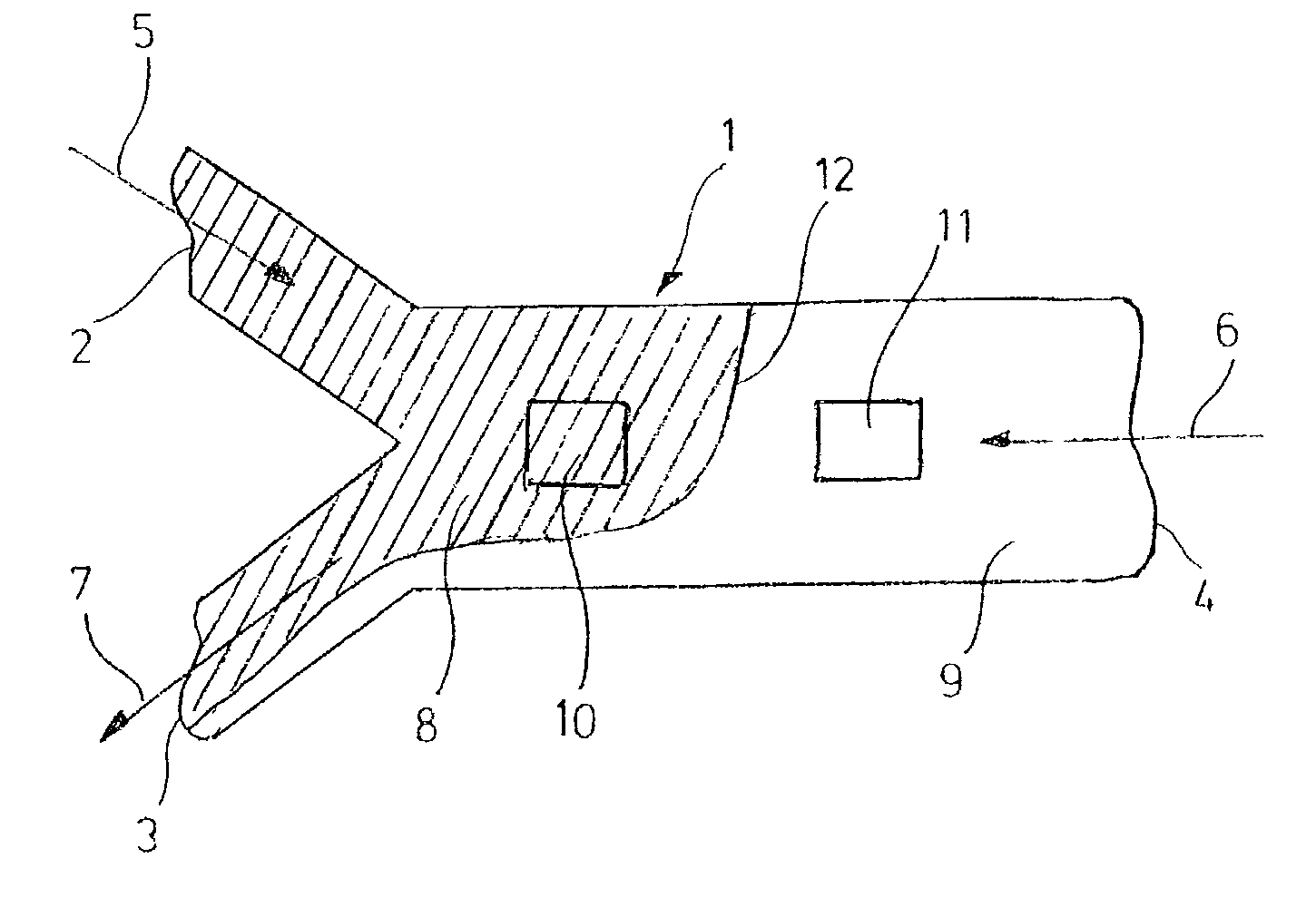
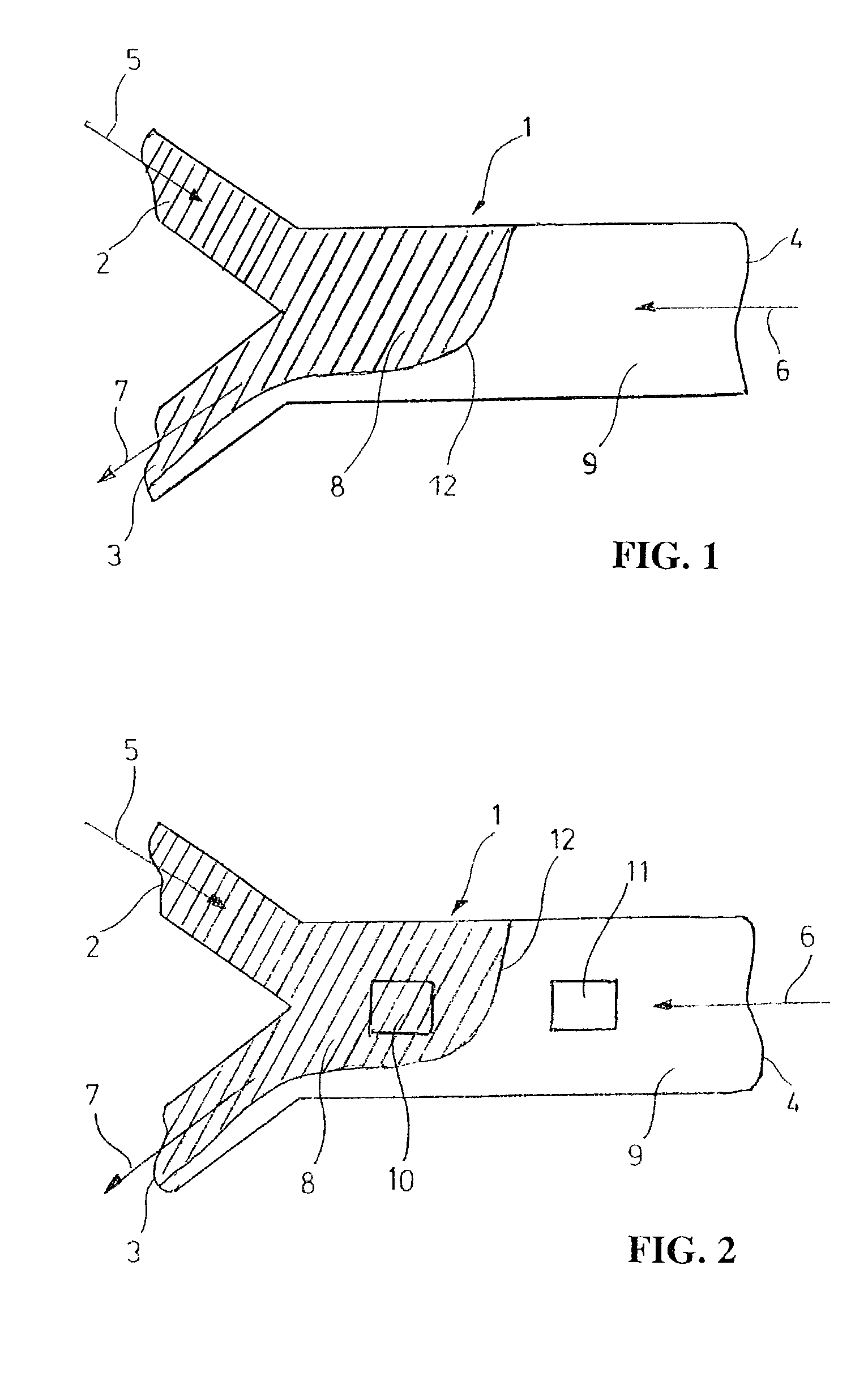
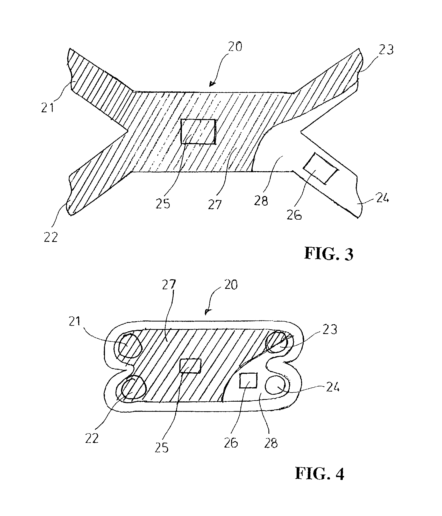
[0017]Selective treatment of a sensing surface in a flow cell may also be used for partial deactivation of the sensing surface. In this case, the sensing surface may contain functional groups which need to be activated by an activating agent to form reactive groups capable of reacting with an analyte-specific ligand to be immobilized on the sensing surface. After activation of the sensing surface, the selective treatment described above may be used to treat the sensing surface area extending from the inlet port up to the vicinity of the detection area or areas with a deactivating agent in order to deactivate that part of the sensing surface. By deactivating the inlet portion of the sensing surface in this manner, the ligand to be immobilized on the sensing surface will not be attached to the sensing surface area preceding the detection area or areas. When sample is subsequently passed over the sensing surface, the deactivation performed will prevent analyte from being bound to the sensing surface on its way to the detection area or areas. In other words, the depletion of analyte in the sample fluid when passing through the flow cell to the detection area or areas will be minimized.
[0018]Another use of the above-mentioned embodiment is for obtaining rapid replacement of a fluid contacting a detection area within the flow cell with a fluid whose interaction with the sensing area is to be studied. This is, for example, useful for studying reaction kinetics. In a first state, the interface between the test fluid and the counter-flowing blocking fluid is positioned to be close to but not extending into or past the detection area. In a second state, the counter-flow is decreased or stopped and the test fluid is discharged at the second (downstream) end of the flow cell instead of at the first (upstream) end, permitting the test fluid to rapidly displace the blocking fluid and contact the detection area(s).

Problems solved by technology

A shortcoming of the methods and systems described in WO 99 / 36766 is, however, that selective contacting of a desired fluid with different areas of the sensing surface is only possible laterally, i.e. transversely to the flow path extension between the flow cell ends.

Method used


Image

  • Flow cell method
  • Flow cell method
  • Flow cell method

Examples


example 1

[0063]Deactivation of an activated inlet area of a flow cell to increase the mass transport to a sensing area

[0064]A BIACORE S51® instrument (Biacore AB, Uppsala, Sweden) was used. The instrument includes a Y-channel flow cell of the type illustrated in FIGS. 5A to 5C. As sensor chip was used Sensor Chip CM5 (Biacore AB), which supports a gold surface with a covalently linked carboxymethyl-modified dextran polymer hydrogel. The optical system measures three detection spots located centrally on the sensing surface forming one channel wall of the flow cell.

[0065]1. Materials

[0066]Ligand: Biotin-jeffamine conjugate, Mw 374.5 (made in-house), 2 mM, 1.75 mg in 2386 μl of 10 mM borate, pH 8.5

[0067]Analyte: Biotin-antibody (from Biotin Kit, Biacore AB)

[0068]Coupling reagent: Amine coupling kit (Biacore AB), EDC / NHS (N-ethyl-N-dimethylaminopropylcarbodiimide and N-hydroxysuccinimide)

[0069]Drive buffer: PBS pH 7.2

[0070]Deactivating reagent: Ethanolamine

[0071]2. A. Sensitization of sensor chi...


PUM

PropertyMeasurementUnit
flow rateaaaaaaaaaa
flow rateaaaaaaaaaa
flow ratesaaaaaaaaaa

Abstract

A method of operating an analytical flow cell device comprising an elongate flow cell having a first end and a second end, at least two ports at the first end and at least one port at the second end, comprises introducing a laminar flow of a first fluid at the first end of the flow cell, and a laminar counter flow of a second fluid at the second end. Each fluid flow is discharged at the first end or the second end, and the position of the interface between the first and second fluids in the longitudinal direction of the flow cell is adjusted by controlling the relative flow rates of the first and second fluids. Also disclosed are a method of analyzing a fluid sample for an analyte, a method of sensitizing a sensing surface, and a method of contacting a sensing surface with a test fluid.

Description

BACKGROUND OF THE INVENTION[0001]1. Field of the Invention[0002]The present invention generally relates to the control of a fluid flow over a surface, especially a sensing surface, within a flow cell of an analytical device and, more specifically, to the use of laminar flow cell techniques to position a fluid flow over desired surface areas within a flow cell.[0003]2. Description of the Related Art[0004]Flow cells are used extensively nowadays in a variety of analytical systems. Typically, the flow cell has an inlet opening, a flow channel and an outlet opening. A sample fluid to be investigated is introduced through the inlet opening, passes through the flow channel and leaves the flow cell through the outlet opening. In the flow channel, the sample fluid can be analyzed. The flow cell may have more than one inlet opening and optionally more than one outlet opening to permit desired manipulations of the flow pattern within the flow cell.[0005]In one type of flow cell, the flow chan...

Claims


Application Information

Patent Timeline
Patent Type & Authority Patents(United States)
IPC IPC(8): G01N1/10G01N21/05G01N
CPCG01N21/05Y10T436/2575Y10T436/118339
Inventor ROOS, HAKANMAGNUSSON, KJELLTIDARE, MATTIAS
Owner GE HEALTHCARE BIO SCI CORP
Learn More