Workpiece welding process

a welding process and workpiece technology, applied in the direction of welding/cutting media/materials, welding apparatus, manufacturing tools, etc., can solve the problems of distortion of welds, inability to achieve desirable welding strength on some occasions, and small welded area of workpieces, etc., to achieve the effect of reducing the amount of energy, and enhancing the overall energy efficiency

Inactive Publication Date: 2006-03-21
HONDA MOTOR CO LTD
View PDF16 Cites 25 Cited by
  • Summary
  • Abstract
  • Description
  • Claims
  • Application Information

AI Technical Summary

Benefits of technology

[0007]Accordingly, it is an object of the present invention to provide a welding process that can weld a workpiece efficiently and securely irrespective of shape and material of the workpiece.
[0011]The workpiece welding process is designed to effectively utilize thermal energy contained in the high-density energy beam by controlling the above distance, and to reduce the amount of energy to be provided to an arc welding machine, so that energy efficiency as a whole may be enhanced.

Problems solved by technology

In the welding utilizing a high-density energy beam, however, the ratio of spread versus penetration of the weld is smaller, and thus when thick plates were overlapped and welded together, a welded area of the workpieces would be so small that a desirable level of welding strength could not be secured on some occasions.
On the other hand, the arc welding would cause distortion of the weld to occur in some instances as a result of a great amount of energy applied; therefore, it should be noted that variations in the quality of welded surfaces might be produced by instability of arc discharge.
Moreover, the arc welding also has the disadvantage of a lower welding speed.

Method used


Image

  • Workpiece welding process
  • Workpiece welding process
  • Workpiece welding process

Examples


Embodiment Construction

[0016]A detailed description will be given of an embodiment of the present invention.

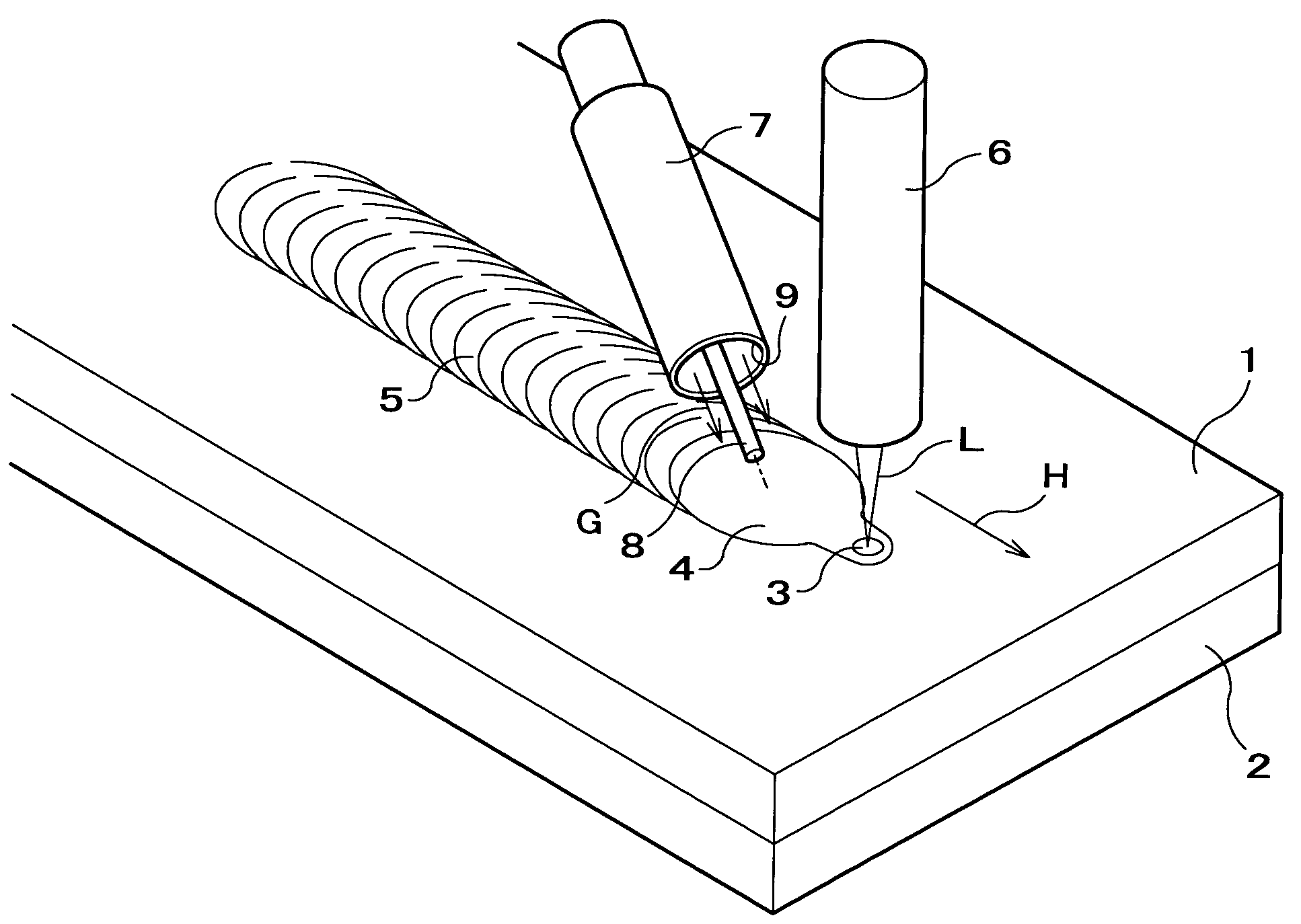
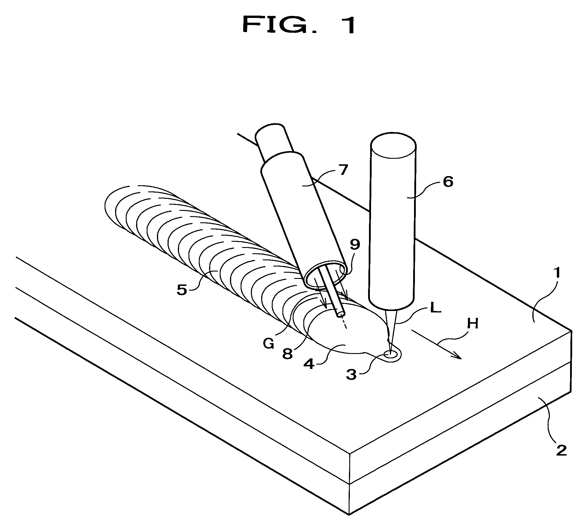
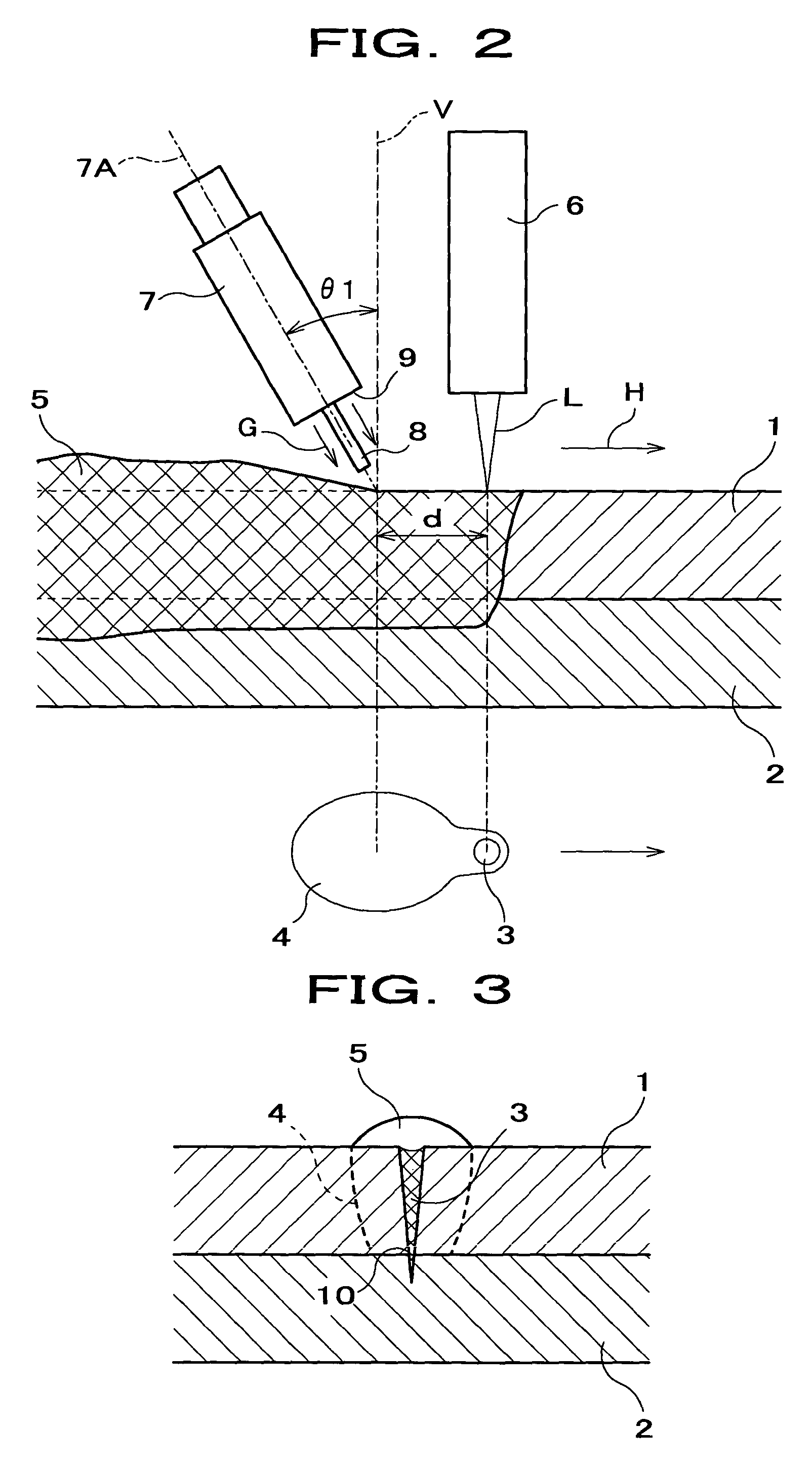
[0017]FIG. 1 is a perspective view illustrating welding of plates utilizing a welding process of the present embodiment, FIG. 2 is a side view of FIG. 1, and FIG. 3 is a front view in cross section of FIG. 1.

[0018]As shown in FIG. 1, the welding process of the present embodiment is a process in which plates 1, 2 as workpieces are welded utilizing a welding process with emission of a laser light L as a high-density energy beam and a welding process with an arc discharge in combination. Herein, the welding is performed toward a welding direction indicated by an arrow H; i.e., a laser light L is first emitted onto overlapped plates 1, 2 to form a molten portion 3 (hereinafter referred to as laser molten weld pool), and thereafter an arc discharge is performed to form a molten portion 4 (hereinafter referred to as arc molten weld pool). A bead 5 formed as a result of solidification of the arc molten wel...


PUM

PropertyMeasurementUnit
fundamental wavelengthaaaaaaaaaa
wavelengthaaaaaaaaaa
lead angle θ1aaaaaaaaaa

Abstract

A laser light L is emitted from a laser light source 6 to workpieces 1, 2, to form a laser molten weld pool 3, and immediately thereafter, an arc molten weld pool 4 is formed using an arc welding machine 7; thereby plates 1, 2 are welded. The arc welding machine 7 is provided with a filler wire to form a bead 5 on the plate 1. With the welding process according to the present invention, workpieces can be efficiently and securely welded regardless of shape and material of the workpieces.

Description

TECHNICAL FIELD[0001]This invention relates to a welding process performed utilizing a high-density energy beam and an arc discharge.BACKGROUND ART[0002]Welding processes used for welding a workpiece in the form of a sheet, plate or the like includes: welding which utilizes a high-density energy beam such as a laser light and an electron beam, and arc welding such as MIG (Metal Inert Gas) welding and TIG (Tungsten Inert Gas) welding.[0003]The welding with a high-density energy beam is a process in which density of energy applied to a workpiece is very high, and thus incorporates advantageous features such as a higher welding speed and a narrower width of a bead formed on the workpiece during the welding process.[0004]In contrast, the arc welding is a process in which a larger amount of energy may be applied to a workpiece per unit of time, despite a lower welding speed, and may thus lend itself to welding of a thick plate. The arc welding also has the advantage of improved quality o...

Claims


Application Information

Patent Timeline
Patent Type & Authority Patents(United States)
IPC IPC(8): B23K26/00B23K9/00B23K9/16B23K26/21B23K26/24B23K26/346B23K103/04B23K103/10
CPCB23K9/173B23K28/02B23K26/246B23K26/1429B23K26/244B23K26/348
Inventor TAKIKAWA, MASATOYAHABA, TAKANORIICHIYAMA, YASUTOMOUKENA, TOSHIYASUSONODA, HIROBUMIOKUYAMA, KENJIIBUKURO, JUNICHI
Owner HONDA MOTOR CO LTD
Why Eureka
Try Eureka