Active night vision cooling system

a cooling system and active technology, applied in lighting and heating devices, electric apparatus casings/cabinets/drawers, instruments, etc., can solve the problems of affecting vehicle styling, difficult to interpret, and high cost of far-infrared cameras, so as to maximize the life of cooling devices, minimize operating noise, and efficiently adjust the temperature of light sources

Inactive Publication Date: 2006-03-21
LEAR CORP
View PDF6 Cites 78 Cited by
  • Summary
  • Abstract
  • Description
  • Claims
  • Application Information

AI Technical Summary

Benefits of technology

[0013]Another advantage of the present invention is that it minimizes operating noise generated by the cooling system and efficiently adjusts the temperature of the light source.
[0014]Furthermore, the present invention maximizes the life span of cooling devices contained within the thermal control system through adjustment of cooling device cycle time.
[0015]Moreover, the present invention is designed such that it may be utilized within an interior cabin of a vehicle. Interior cabin use allows for easier temperature control of the light source and minimizes risk of exposure to water or condensation on the light source.
[0016]Yet another advantage of the present invention is that it provides a thermal control system that is compact in design and may be located in various locations within an interior cabin of a vehicle.

Problems solved by technology

Externally mounted cameras can negatively affect vehicle styling.
Far-infrared cameras are also costly to manufacture and generate images that have poor contrast, which can be difficult to interpret.
Filtering a significant portion of energy from a bulb is expensive, energy inefficient, and generates undesired thermal energy.
Also, filter positioning is limited in incandescent applications, since the filter must be located proximate an associated light source.
As well, multiple incandescent sources are often required to provide requisite illumination, thus increasing complexity and costs.
Exterior mounted light sources or cameras are undesirable due to risk of damage during a vehicle collision.
Night vision components are relatively expensive and, as a result, protection of the components is desired.
Also, exterior mounted light sources and cameras are susceptible to theft.
Additionally, external mounting of sources and cameras can limit and compromise vehicle design and styling, can be esthetically displeasing, and can increase exposure of the devices to dust and debris.
Exposure to dust and debris negatively effects performance of the sources and cameras.
When the sources and cameras are dirty, light transmission and reception can be substantially reduced, compromising system performance.
Exterior mounted illumination sources have additional associated disadvantages.
A significant disadvantage is controlling the wavelength of the illumination beam.
When a night vision system is operated outside this range the received illumination decreases negatively, affecting image quality of the active night vision system.
Since external temperatures vary considerably, it is difficult to control the temperature of a diode laser.
Also, when mounted externally, a risk of exposure to water exists, which can render the laser inoperable.
Sealing and housing problems due to thermal energy management may also arise when weatherproofing diode lasers.
Thus it is difficult to achieve commonality for light sources between different vehicles.
Designing different light sources for different vehicles is costly.

Method used


Image

  • Active night vision cooling system
  • Active night vision cooling system
  • Active night vision cooling system

Examples


Embodiment Construction

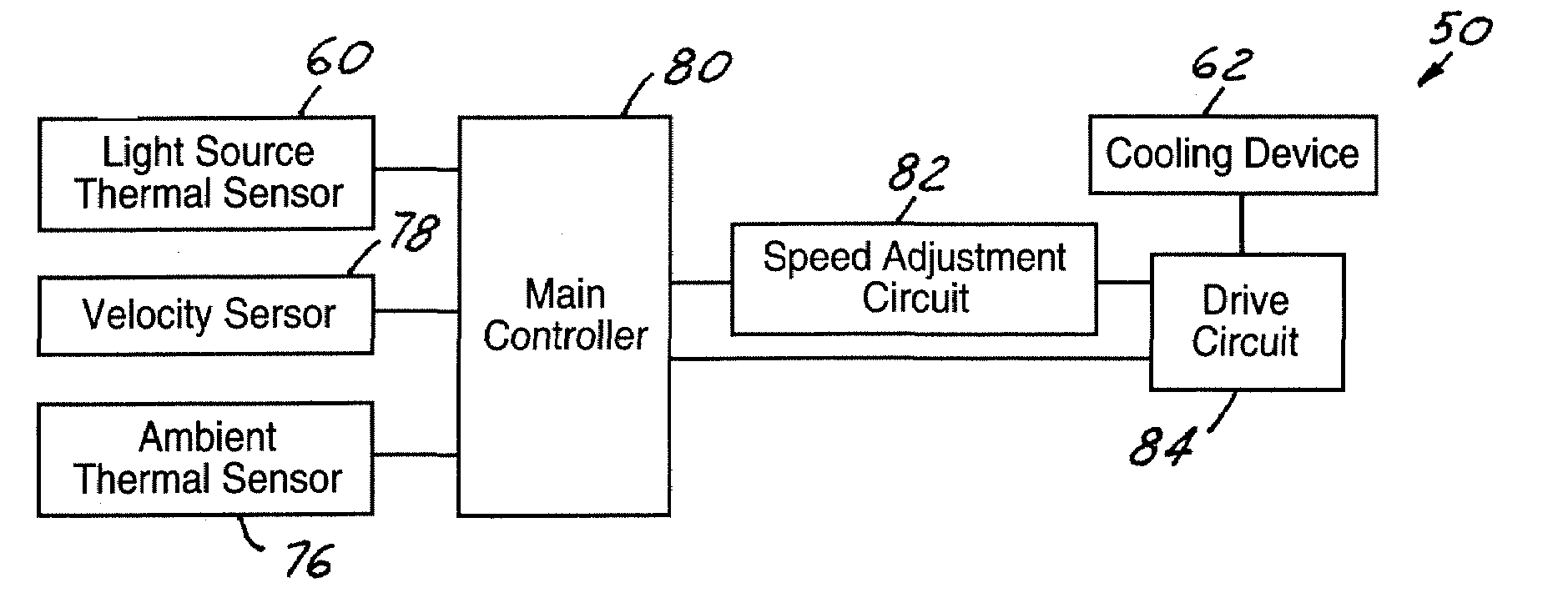
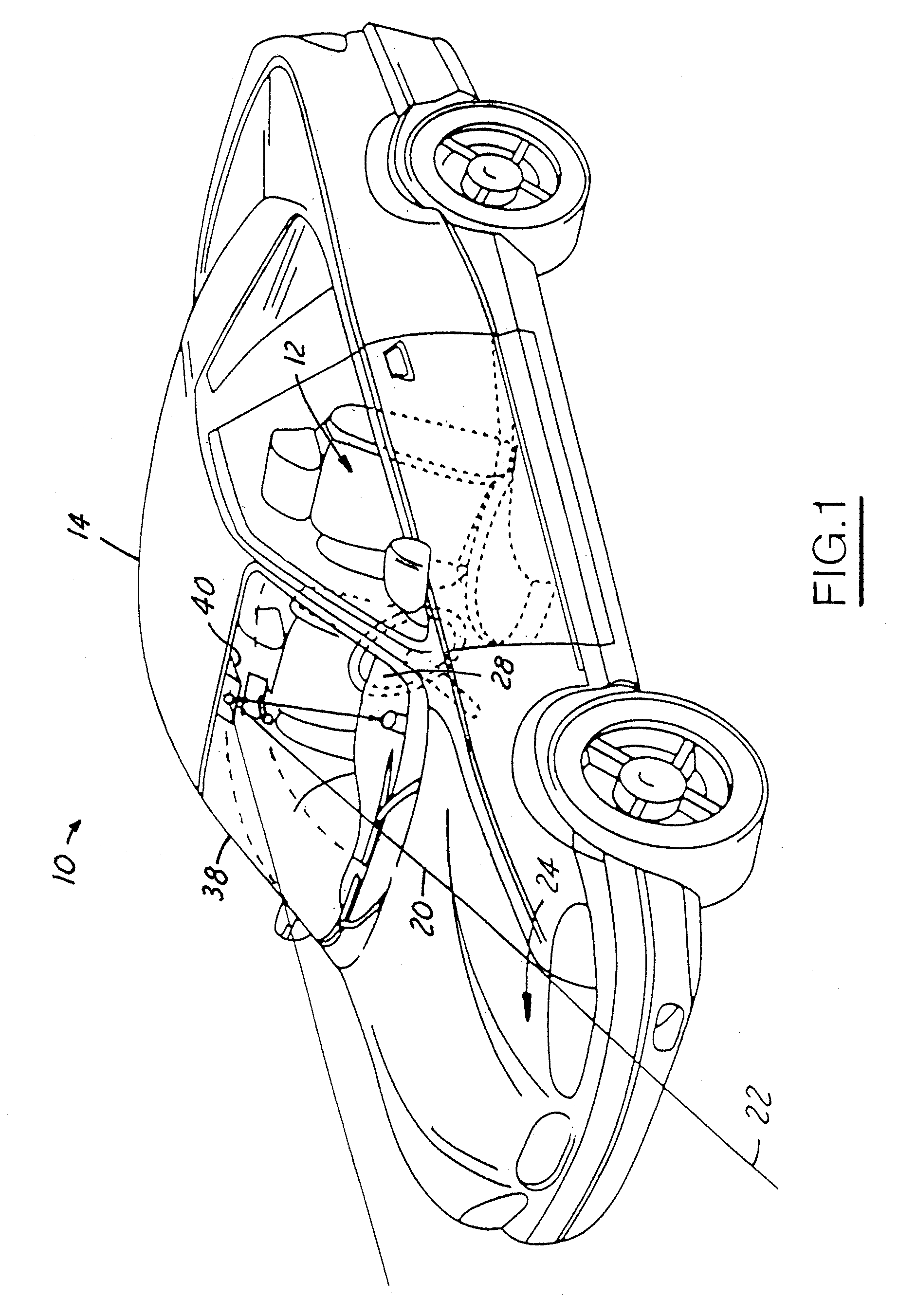
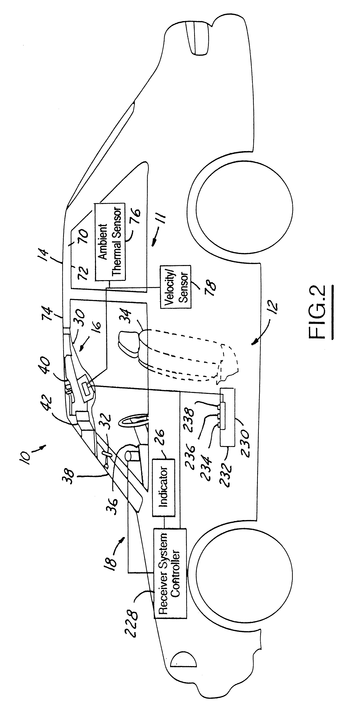
[0026]In the following figures the same reference numerals will be used to refer to the same components. While the present invention is described with respect to a system and method of thermally controlling the operating range of a light source of an active night vision system, the present invention may be applied in various applications where near infrared imaging is desired, such as in adaptive cruise control applications, collision avoidance and countermeasure systems, and in image processing systems. The present invention may be applied during day-time hours or at night. The present invention may be applied in various types and styles of vehicles as well as in non-vehicle applications.

[0027]Also, although the present invention is described with respect an illumination system that is configured to be mounted within an overhead console of a vehicle, the present invention may be applied to light sources within or exterior to an interior cabin of a vehicle, as well as to other light...


PUM


Abstract

A thermal control system (11) for a light source (46) of a vision system (10) includes a cooling assembly (61) that has a cooling device (62) and is thermally coupled to the light source (46). A thermal sensor (60) is thermally coupled to the light source (46) and generates a light source temperature signal. A control circuit (50) is coupled to the cooling assembly (61) and to the thermal sensor (60) and operates the cooling device (62) when the light source temperature signal is above a minimum temperature limit.

Description

BACKGROUND OF INVENTION[0001]The present invention relates to night vision systems, and more particularly, to a system and method of thermally controlling the operating range of a light source of an active night vision system.[0002]Night vision systems allow a vehicle occupant to better see objects during relatively low visible light level conditions, such as at nighttime. Night vision systems typically are classified as either passive night vision systems or active night vision systems. Passive systems simply detect ambient infrared light emitted from objects within a particular environment. Active systems utilize a light source to illuminate a target area and subsequently detect infrared light reflected off objects within that area.[0003]Passive systems typically use far-infrared cameras characterized by low resolution and a relatively narrow field-of-view. Such cameras must be located on the vehicle exterior in order to acquire requisite infrared energy in the operating environme...

Claims


Application Information

Patent Timeline
Patent Type & Authority Patents(United States)
IPC IPC(8): H01L31/00F21V29/00F41G1/32F41G1/34G02B23/12H01J61/52
CPCB60R1/00B60R2300/106B60R2300/8093B60R2300/40B60R2300/8053B60R2300/205
Inventor FAYTLIN, ALEXANDER B.MOORE, MARK
Owner LEAR CORP
Why Eureka
Try Eureka