
Focused ion beam system

a focused ion beam and beam system technology, applied in liquid/fluent solid measurement, machines/engines, instruments, etc., can solve the problems of difficult to create specimens, low resolution of sem, and difficulty in mounting miniature specimen pieces in specimen holders

Active Publication Date: 2006-03-21
HITACHI HIGH-TECH CORP
View PDF14 Cites 15 Cited by
  • Summary
  • Abstract
  • Description
  • Claims
  • Application Information

AI Technical Summary

Benefits of technology

[0006]It is an object of the present invention to provide a focused ion beam system which is capable of creating a specimen for observation by a TEM, and facilitating works for mounting the specimen in a specimen holder associated with the TEM.

Problems solved by technology

The SEM, however, has the disadvantage of a low resolution.
The TEM, though having a high resolution, involves difficult works for creating specimen.
Thus, the operator experiences difficulties in mounting a cut-out miniature specimen piece in a specimen holder.
Since the small specimen piece itself causes difficulties in handling, the operator is highly likely to drop, lose, or damage the specimen piece.
In addition, difficulties are also encountered in cutting out a specimen piece including a site under observation, leading to a long time taken for fabricating such a specimen piece.

Method used


Image

  • Focused ion beam system
  • Focused ion beam system
  • Focused ion beam system

Examples


Embodiment Construction

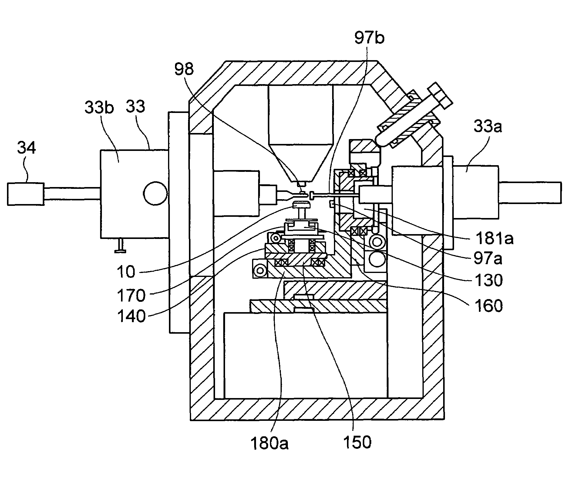
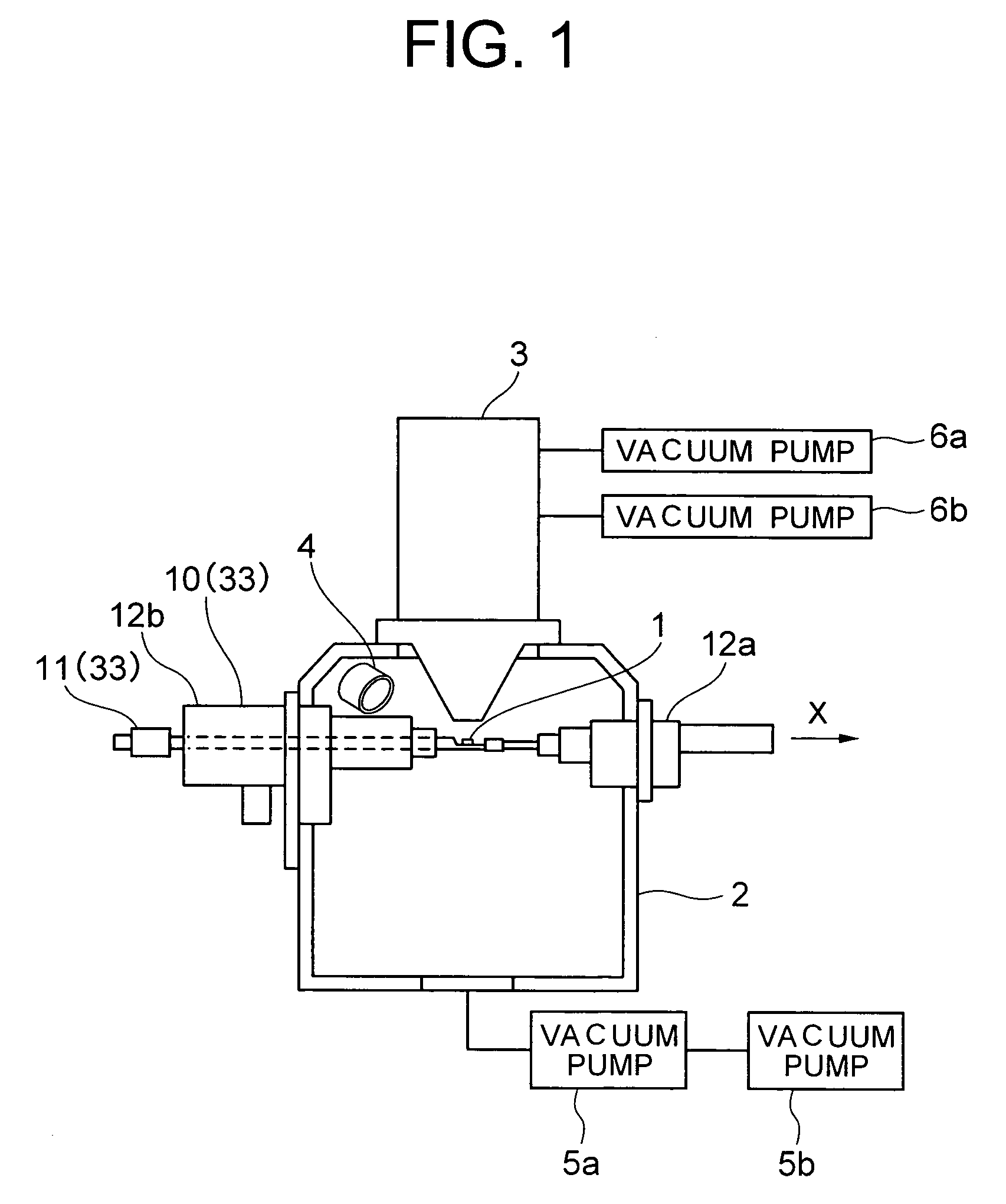
[0019]Referring now to FIG. 1, description will be made on the configuration of a focused ion beam system which is mounted with a TEM specimen holder. The illustrated focused ion beam system comprises a specimen chamber 2; an FIB column 3 disposed above the specimen chamber 2; a side entry stage 10 disposed along an x-axis direction; a secondary electron detector 4 for detecting secondary electrons; and vacuum pumps 5a, 5b and 6a, 6b for evacuating the specimen chamber 2 and FIB column 3, respectively.

[0020]The side entry stage 10 includes a specimen holder 11 for holding a specimen 1 (hereinafter called the “TEM specimen holder”); an x-micromotion driver 12a for moving the specimen 1 in the x-direction; and a yzt-micromotion driver 12b having a tilt mechanism for moving the specimen 1 in the y- and z-directions (optical axis) and rotating the specimen 1 about a tilt axis. The x-micromotion driver 12a and yzt-micromotion driver 12b are mounted on opposing side surfaces of the specim...


PUM


Abstract

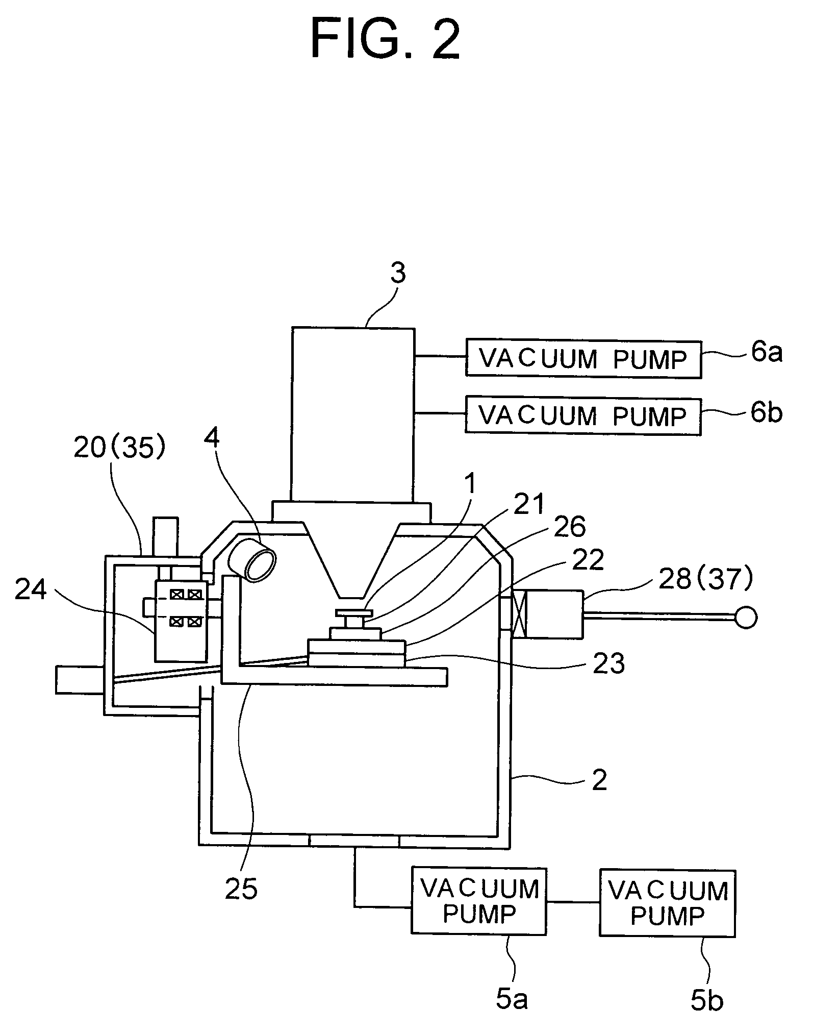
A focused ion beam system comprises a specimen chamber, a FIB column, a SEM stage, a side entry stage, a TEM specimen holder, a micro-sampling manipulator, and a SEM holder exchanger chamber. The SEM stage comprises an x-table, a y-table, a z-table, a rotation table, and a tilt table for moving a specimen. The side entry stage comprises an x-micromotion driver and a yzt-micromotion driver which are disposed in the specimen chamber to oppose each other. The x-micromotion driver is disposed in a hollow area defined in a tilt shaft provided for the tilt table.

Description

BACKGROUND OF THE INVENTION[0001]The present invention relates to a focused ion beam system which is suitable for use in fabricating a specimen for a transmission electron microscope (TEM), a scanning electron microscope (SEM), and the like, and more particularly, to a focussed ion beam system which is suitable for creating a specimen for TEM.[0002]The TEM and SEM have been used for analyzing semiconductor devices, and a focused ion beam system has been utilized for processing materials with a focussed ion beam to fabricate specimen therefor. The focused ion beam system is configured to share a specimen holder with TEM or SEM. Specifically, the focused ion beam system can removably mount a TEM specimen holder or a SEM specimen holder. Therefore, after a specimen has been fabricated by the focussed ion beam system, the specimen holder can be removed from the focussed ion beam system, with the resulting specimen held therein, and mounted to the TEM or SEM for observing the specimen.[0...

Claims


Application Information

Patent Timeline
IPC IPC(8): H01J37/20G01N1/32G01N1/28H01J37/18H01J37/30H01J37/305H01J37/317
CPCH01J37/185H01J37/3056H01J37/20H01J2237/31749
Inventor SUZUKI, WATARUHAZAKI, EIICHI
Owner HITACHI HIGH-TECH CORP
Learn More