Automatic video system using multiple cameras

a video system and camera technology, applied in the field of video systems and composition of multiple digital images, can solve the problems of mccutchen suffering problems at image boundaries, systems attempting to integrate multiple images have failed to meet the needs or goals of users, and the cost of such systems has prevented them from becoming common and in wide spread us

Inactive Publication Date: 2006-03-21
FUJIFILM BUSINESS INNOVATION CORP
View PDF113 Cites 675 Cited by
  • Summary
  • Abstract
  • Description
  • Claims
  • Application Information

AI Technical Summary

Benefits of technology

[0021]New CMOS camera chips will be both better and far less expensive than the current widely used CCD camera chips. By tracking shape, motion, and/or color cues, the location of subjects in the room can be determined. Unlike prior art tracking systems using steerable cameras, the subject is always in view and can't get “lost.” The camera array can be used as a sensor to control conventional steerable cameras. Additionally, video images from adjacent cameras are digitally composited to gi

Problems solved by technology

However, technical challenges and costs have prevented such systems from becoming common and in wide spread use.
Systems attempting to integrate multiple images have failed to meet the needs or goals of users.
However, the approach taught in McCutchen

Method used


Image

  • Automatic video system using multiple cameras
  • Automatic video system using multiple cameras
  • Automatic video system using multiple cameras

Examples


Embodiment Construction

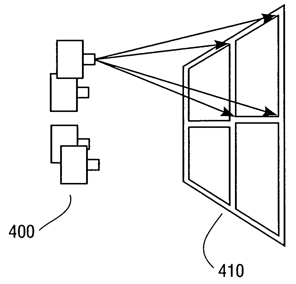
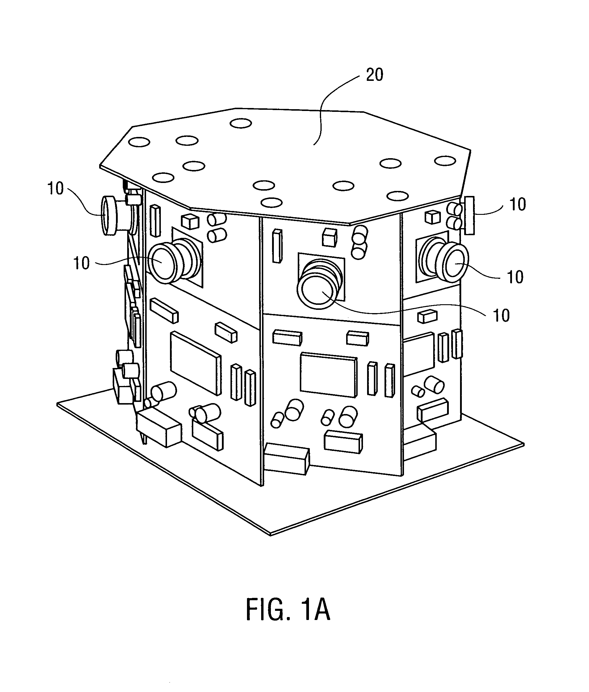
[0050]Referring now to the drawings, wherein like reference numerals designate identical or corresponding parts, and more particularly to FIG. 1A thereof, there is illustrated is an example of a circular array of video cameras according to the present invention. In FIG. 1A, multiple video cameras 10 are mounted on a rigid substrate 20 such that each camera's field of view overlaps or abuts that of its neighbor. The resulting images are aligned using digital warping and combined to form a large composite image. The result is a seamless high-resolution video image spanning the field of view of all cameras. If the cameras are mounted in fixed positions relative to each other, image registration between the different cameras is also fixed, and the same composition function can be used for each frame. Thus the interpolation parameters need only be calculated once, and the actual image composition can be done quickly and efficiently, even at video rates.

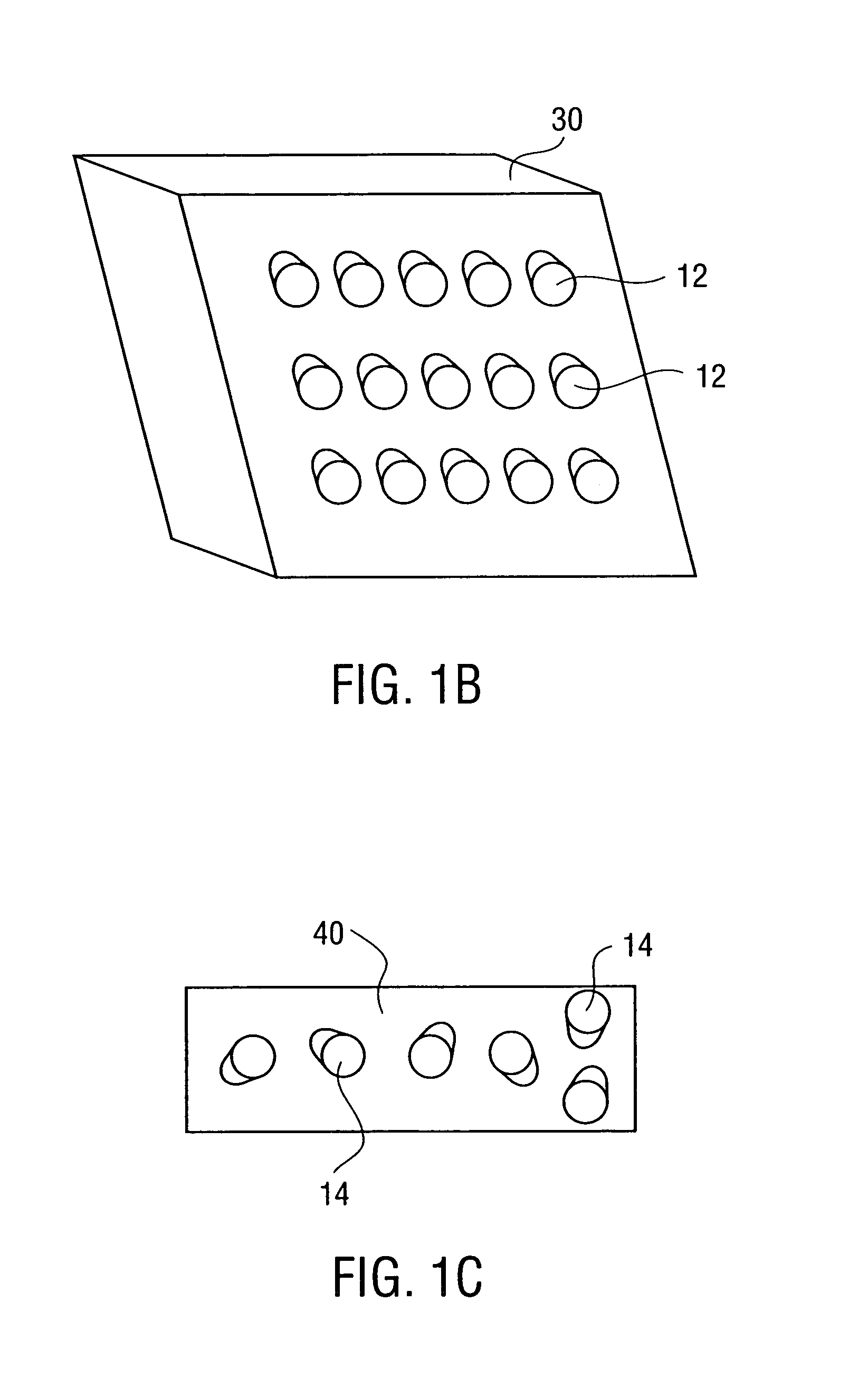
[0051]Other configurations of camer...


PUM


Abstract

A camera array captures plural component images which are combined into a single scene from which “panning” and “zooming” within the scene are performed. In one embodiment, each camera of the array is a fixed digital camera. The images from each camera are warped and blended such that the combined image is seamless with respect to each of the component images. Warping of the digital images is performed via pre-calculated non-dynamic equations that are calculated based on a registration of the camera array. The process of registering each camera in the arrays is performed either manually, by selecting corresponding points or sets of points in two or more images, or automatically, by presenting a source object (laser light source, for example) into a scene being captured by the camera array and registering positions of the source object as it appears in each of the images. The warping equations are calculated based on the registration data and each scene captured by the camera array is warped and combined using the same equations determined therefrom. A scene captured by the camera array is zoomed, or selectively steered to an area of interest. This zooming- or steering, being done in the digital domain is performed nearly instantaneously when compared to cameras with mechanical zoom and steering functions.

Description

COPYRIGHT NOTICE[0001]A portion of the disclosure of this patent document contains material which is subject to copyright protection. The copyright owner has no objection to the facsimile reproduction by anyone of the patent document or the patent disclosure, as it appears in the Patent and Trademark Office patent file or records, but otherwise reserves all copyright rights whatsoever.BACKGROUND OF THE INVENTION[0002]1. Field of the Invention[0003]This invention relates to video systems and composition of multiple digital images. The invention is more particularly related to the composition of multiple digital images each captured by an individual camera of a camera array, and to a method of warping at least portions of images so that the images can be combined, without overlap or inconsistent pixels, into a single image. The invention also related to the registration of multiple cameras and the determination of a transformative equation that allows fast warping and summation of plu...

Claims


Application Information

Patent Timeline
IPC IPC(8): H04N5/225H04N5/232H04N7/18G06T3/00G06T5/00G06T7/00H04N1/387H04N5/247H04N13/239H04N13/243
CPCG06T3/4038G06T5/006G06T7/0022G06T7/0028H04N5/23238G03B37/04H04N5/2628H04N13/0022H04N13/0242H04N5/247G06T2207/10012H04N13/0239H04N2013/0081H04N2013/0088G06T7/97G06T7/33H04N13/243H04N13/239H04N13/128H04N23/698H04N23/90
Inventor FOOTE, JONATHANAHMAD, SUBUTAIBORECZKY, JOHN
Owner FUJIFILM BUSINESS INNOVATION CORP
Why Eureka
Try Eureka