Audio apparatus

Inactive Publication Date: 2006-03-21
NOKIA MOBILE PHONES LTD
View PDF12 Cites 13 Cited by
  • Summary
  • Abstract
  • Description
  • Claims
  • Application Information

AI Technical Summary

Benefits of technology

[0011]This provides the advantage of enabling the effects of the demodulation process and the transducer conversion characteristics on th

Problems solved by technology

As a result significant coloration (i.e. a shift of signal power with respect to frequency) and distortion are introduced onto the demodulated audio signal as a result of the interaction of the ultrasonic wave with the non-linear medium.
However, for the self-demodulation to occur high ultrasonic sound pressure levels are required.
The variable transducer frequency response can signific

Method used


Image

  • Audio apparatus
  • Audio apparatus
  • Audio apparatus

Examples


Embodiment Construction

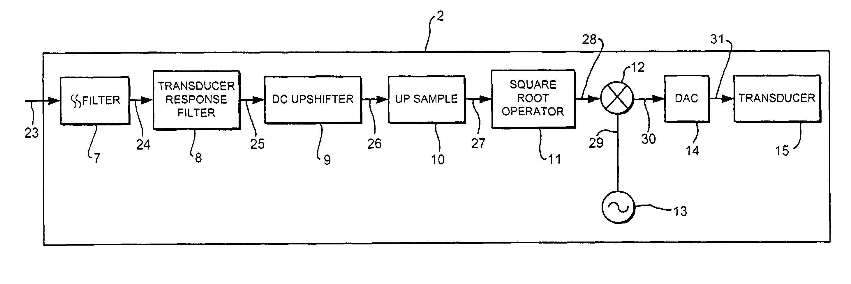
[0022]FIG. 3 shows a radiotelephone 1 with audio apparatus 2, a speech decoder 3, a channel decoder 4, a receiver 5 and an antenna 6. In operation the receiver 5 receives a speech encoded digital signal 20 from a base station (not shown) via antenna 6. The receiver 5 demodulates the received digital signal 20 and passes the demodulated signal 21 to channel decoder 4 which corrects for errors that may have occurred during the transmission process by using error protection bits encoded within the received signal. The receiver 5 typically samples the received signal 20 at 8 kHz. The decoded digital signal 22 is provided to speech decoder 3 which decodes the speech and passes the digital decoded signal 23 to audio apparatus 2 to generate an acoustic representation of the received speech signal as described in detail below. The audio apparatus 2 may be mounted within the radiotelephone 1. Typically however, to obtain the required audio power levels and to support hands free use of the ra...


PUM


Abstract

An audio apparatus comprising a modulator 12 for modulating a first ultrasonic signal 29 with an audio signal to provide a second ultrasonic signal 30; a transducer 15 for converting the second ultrasonic signal 30 into an ultrasonic pressure wave for transmission into a non-linear medium to allow demodulation of the ultrasonic pressure wave and thereby generate an audio pressure wave representative of the audio signal 29, processing means 11 for modifying the audio signal to compensate for the demodulating properties of the non-linear medium; and means 8 for modifying the audio signal to compensate for the conversion characteristics of the transducer 15.

Description

BACKGROUND OF THE INVENTION[0001]This invention relates to audio apparatus, and in particular audio apparatus for radiating an ultrasonic pressure wave with a modulated audio signal.[0002]Audio spotlighting, using a parametric audio system, provides a means for projecting highly directional beams of audible sound. This technology employs the non-linearity of a compressible material (such as air) to create audible by-products from inaudible ultrasound. This technique exploits an acoustic phenomenon called self-demodulation where low frequency audio beams of high directivity are generated from a high amplitude ultrasonic beam that has been modulated with an audio signal. Self-demodulation generates new frequencies in the received sound spectra based on the envelope frequency (i.e. the required audio signal) in a process akin to AM demodulation. Thus this technique provides a beam of audio sound with the focused directional properties of the original ultrasonic carrier beam, allowing d...

Claims


Application Information

Patent Timeline
IPC IPC(8): H04B3/00G11B20/08H04R3/00
CPCH04R3/00G11B20/08
Inventor PHELPS, ANDREW
Owner NOKIA MOBILE PHONES LTD
Why Eureka
Try Eureka