System and method for varying low audio frequencies inversely with audio signal level

a low-frequency, inverse technology, applied in the field of audio speakers, can solve the problem that filters do not immediately cut-off frequencies, and achieve the effect of more accurate simulation of the fletcher-munson curv

Inactive Publication Date: 2006-03-21
HARMAN INT IND INC
View PDF35 Cites 49 Cited by
  • Summary
  • Abstract
  • Description
  • Claims
  • Application Information

AI Technical Summary

Benefits of technology

[0017]It is still another object of the present invention to boost the bass content slowly when the input audio signal decreases and remove the bass boosting quickly when the input audio signal increases such that the bass boost action is not observed by a listener as volume level declines and does not damage audio equipment as volume level increases.
[0020]It is still another object of the present invention to utilize a digital signal filter processing circuit in addition to controlling the filter corner frequency to more accurately mimic the Fletcher-Munson curves.
[0021]Thus, the present invention relates to a method comprising receiving an input audio signal, coupling the input audio signal to a filter circuit to recover the audio signal, adjusting the corner frequency of the filter circuit as the input audio signal changes, utilizing this filter in a feedback configuration thus boosting the bass slowly when the input audio signal decreases, removing the bass boosting quickly when the input audio signal increases, and driving the audio speaker with the automatic boosting compensation.
[0023]Yet, another embodiment of the automatic bass boost compensation circuit is disclosed which utilizes a DSP filter circuit that is particularly useful for more accurate simulation of the Fletcher-Munson curves.

Problems solved by technology

However, filters do not immediately cut-off frequencies at the corner frequency due to the limitations of electronic components.

Method used


Image

  • System and method for varying low audio frequencies inversely with audio signal level
  • System and method for varying low audio frequencies inversely with audio signal level
  • System and method for varying low audio frequencies inversely with audio signal level

Examples


Embodiment Construction

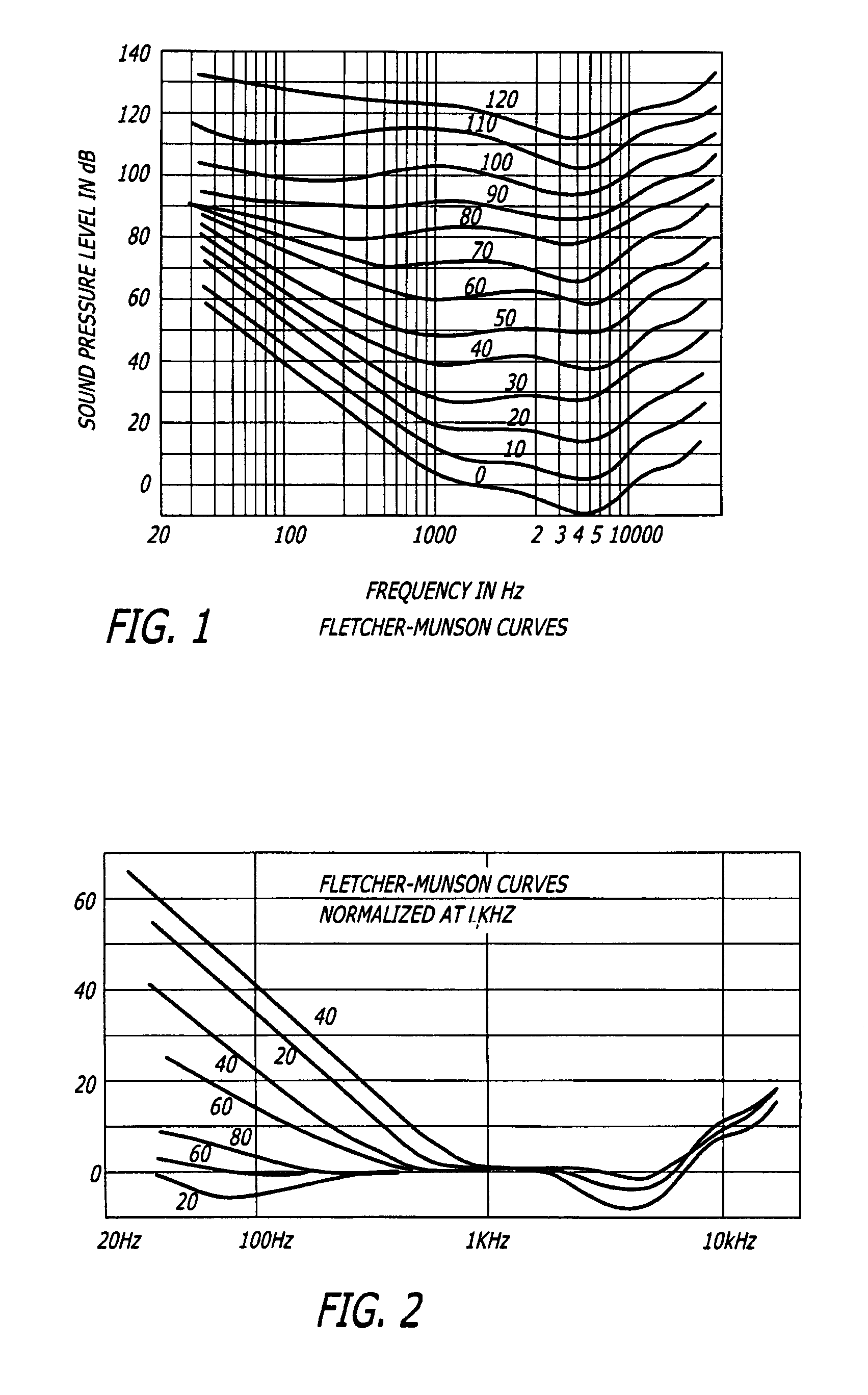
[0037]FIG. 1 illustrates a set of well-known frequency domain relative level curves first developed by Fletcher and Munson in the early 1930's. These frequency domain relative level curves (equal loudness contours) relate to the frequency response of a human ear to the level of signals being heard. As the signal level decreases, research shows that the responsiveness to the signal by the human ear alters, in particular, in relation to this invention, responsiveness to bass frequencies decreases.

[0038]Referring to FIG. 2, a set of frequency domain relative level curves illustrates the results from the Fletcher-Munson curves after being ‘normalized’ at 1 kHz. Since the Fletcher-Munson curves of FIG. 1 are stable at 1 kHz, the curves were normalized at that frequency. The curves were normalized in order to determine the desired output characteristics for a circuit that performs according to the normalized curves. Thus, the filter circuit of the present invention was designed to perform...


PUM


Abstract

The present invention relates to an auto loudness circuit for performing loudness compensation automatically depending on the signal level. When the signal level decreases, loudness compensation is slowly introduced and as the signal level increases, loudness compensation is quickly removed. To do so, the auto loudness circuit utilizes a filter circuit with the characteristic of a first order bass boost. The filter circuit maintains a corner frequency which is proportional to the inverse of audio level in order to mimic the Fletcher-Munson curves. Because the circuit employs a capacitance-multiplier with a first order resistance capacitance filter, the bass boost is inversely proportional to the signal level. Thus, bass boost is achieved automatically as the program content changes so that the listener is unaware of significant changes in program material as signal levels change either through increase or decrease in volume, crescendo or new material.

Description

I. FIELD OF THE INVENTION[0001]The present invention relates in general to audio speakers and in particular to a method and apparatus based upon the characteristics of the Fletcher-Munson curves for obtaining automatic compensation and equalization of program content as the input signal changes.II. BACKGROUND OF THE INVENTION[0002]The Fletcher-Munson findings are well known in the prior art and generally teach that as the signal level of program material is lowered, the responsiveness of the human ear decreases. The result is that at low volume levels, the human ear is less able to hear bass sounds. Presently, many audio systems utilize a manual loudness control to boost low and high-end response at low volume levels in order to compensate for the decreased responsiveness of the human ear. Such a manual loudness control circuit is illustrated in U.S. Pat. No. 4,490,843.[0003]Other circuits relate to improving the sound quality in automotive systems by implementing a controllable bas...

Claims


Application Information

Patent Timeline
Patent Type & Authority Patents(United States)
IPC IPC(8): H03G5/00H03G1/00H03G5/16H03G5/22H03G9/04
CPCH03G1/0047H03G5/22H03G5/165
Inventor BHARITKAR, SUNILSHUTTLEWORTH, TIMOTHY
Owner HARMAN INT IND INC
Why Eureka
Try Eureka