System and method for universal remote access and display of diagnostic images for service delivery

a diagnostic image and universal remote access technology, applied in the field of imaging systems, can solve problems such as image quality problems

Active Publication Date: 2006-03-21
GE MEDICAL TECH SERVICES
View PDF6 Cites 124 Cited by
  • Summary
  • Abstract
  • Description
  • Claims
  • Application Information

AI Technical Summary

Benefits of technology

[0014]The method in accordance with one preferred embodiment comprises the step of sending a troubled image, i.e., an image of poor quality, from a malfunctioning scanner to a data capture device via a local area network using an accepted communications protocol. For example, in the case of medical diagnostic images, the accepted communications protocol is preferably DICOM. The troubled image, in DICOM format, is received and stored by the data capture device on the local area network. The data capture device is in turn programmed to notify a central service facility that a troubled image has been received from a particular scanner. Later the troubled image is sent from the data capture device to the central service facility, where a service support engineer can view the troubled image on his/her workstation and try to diagnose the problem inside the malfunctioning scanner. In accordance with this preferred embodiment, the malfunctioning scanner must be configured to communicate with the data capture device, in the same way that the scanner needs to be configured with any remote DICOM-compatible device. This method allows a central service facility to diagnose image quality problems in scanners that the service center is unable to access directly.
[0015]In accordance with a second preferred embodiment, the scanner need not be configured to communicate with the data capture device. Instead a scanner user who is experiencing image

Problems solved by technology

Instead a scanner user who is experiencing image quality problems on the scanner may

Method used


Image

  • System and method for universal remote access and display of diagnostic images for service delivery
  • System and method for universal remote access and display of diagnostic images for service delivery
  • System and method for universal remote access and display of diagnostic images for service delivery

Examples


Embodiment Construction

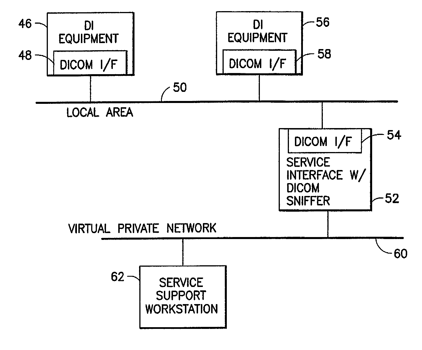
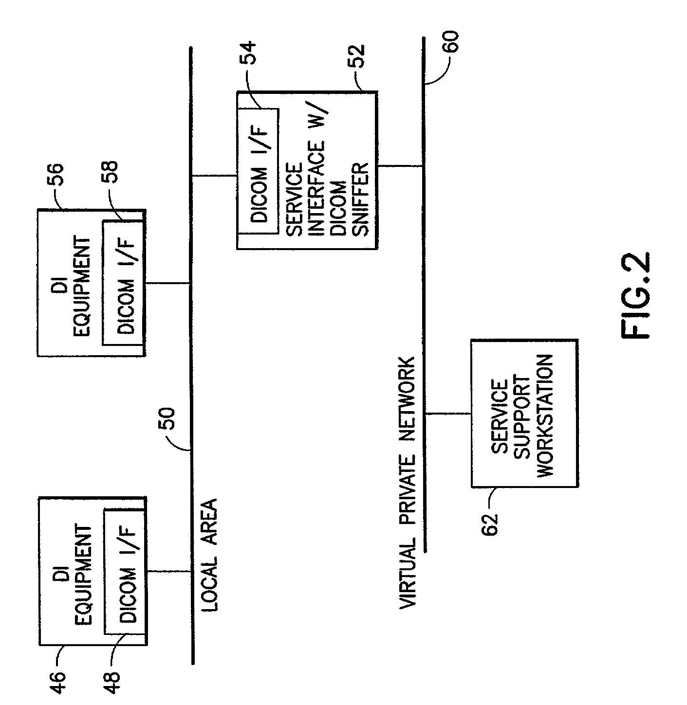
[0024]A DICOM network may comprise scanners of different modalities, a worklist broker (for interfacing an RIS or HIS to a DICOM network), storage devices, and printing devices, all connected to a local area network (LAN). Each DICOM-compatible scanner has the built-in capability to communicate with any one or more remote devices in conformance with the DICOM requirements. As used herein, the term “storage device” includes, but is not limited to, a picture archiving and communications system (PACS) having a viewing station.

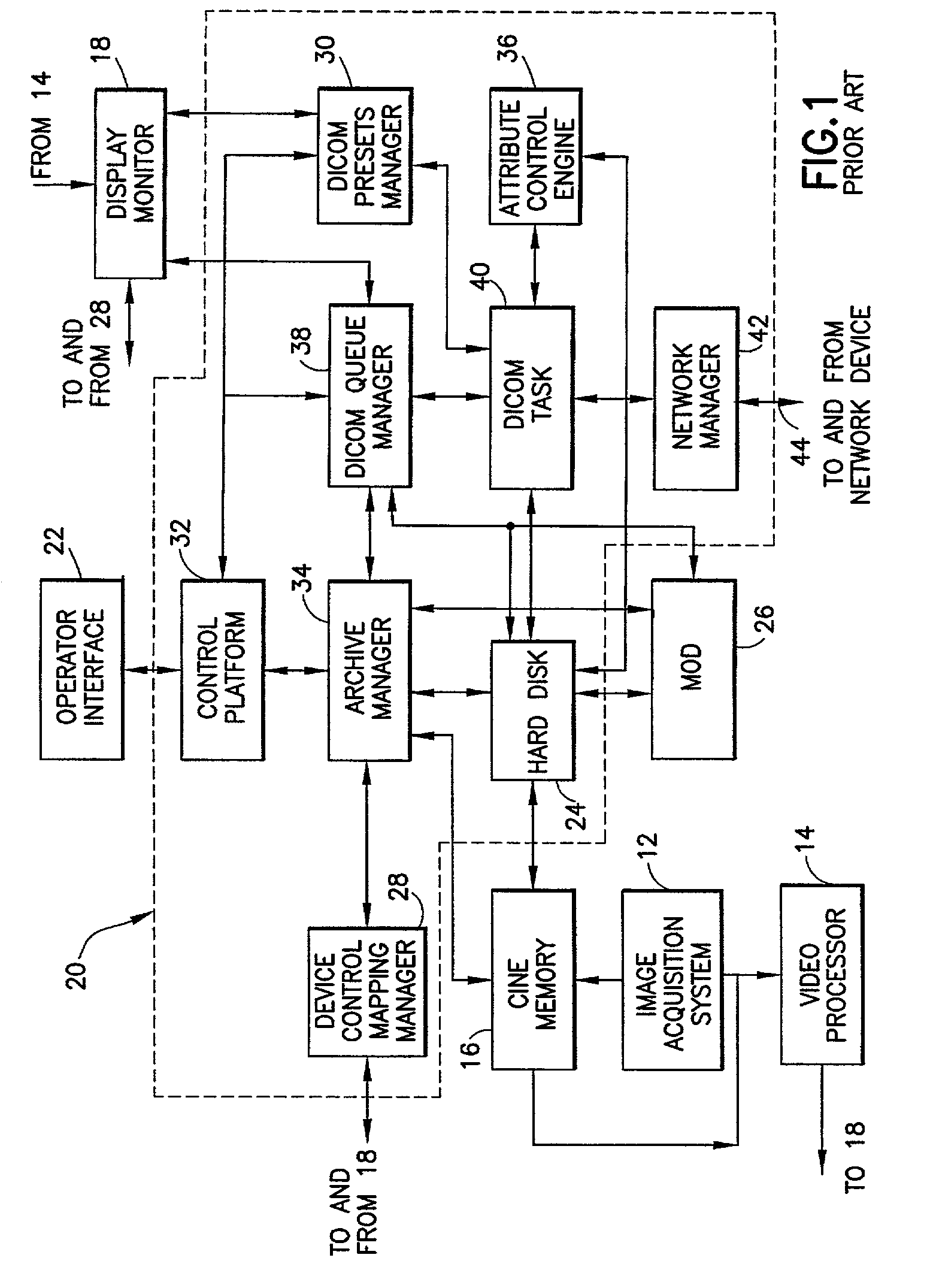
[0025]For the purpose of illustration, portions of a known scanner, namely, a computerized ultrasound imaging system, are represented in FIG. 1. This scanner is programmed to communicate with remote devices over a network in conformance with the DICOM standard. An image acquisition subsystem of known construction acquires images from a patient. During image acquisition, each frame of imaging data is mapped into a gray-scale and / or color imaging format by a video p...


PUM


Abstract

Systems and methods for enabling universal remote access and display of diagnostic images acquired by diagnostic imaging equipment, independent of the identity of the vendor that manufactured the equipment. One system includes a local area network; a scanner capable of sending objects formatted in accordance with a communications protocol, each object incorporating at least one image frame; and a data capture device connected to the local area network and programmed with data capture software to capture an object originating from the scanner in response to that scanner being specified as an object of diagnosis. This system further includes a communications channel, e.g., a virtual private network, for connecting the data capture device to a central service facility. The preferred communications protocol is DICOM. In response to an instruction from the service center, the data capture device on the LAN captures image files from a malfunctioning scanner and forwards them to the service center for diagnosis.

Description

BACKGROUND OF INVENTION[0001]This invention generally relates to imaging systems used in medical diagnostics. In particular, the invention relates to the transfer of digital images from an imaging system over a network to remote devices for archiving, viewing and / or printing.[0002]Modern medical diagnostic imaging systems typically include circuitry for acquiring image data and for transforming the data into a useable form, which is then processed to create a reconstructed image of features of interest within the patient.[0003]The image data acquisition and processing circuitry is referred to as a “scanner”, regardless of the modality, if physical or electronic scanning occurs as part of the imaging process. The particular components of the system and related circuitry, of course, differ greatly between modalities due to their different physics and data processing requirements.[0004]Conventional scanners create two-dimensional images of biological tissue by scanning in a scan plane....

Claims


Application Information

Patent Timeline
IPC IPC(8): G06F15/16G06F15/173H04L12/40A61B5/055A61B5/06A61B6/00A61B8/00G06F11/273H04L12/16H04L12/26H04L29/02H04N1/00H04N1/32
CPCG06F11/0709G06F11/0733G06F11/0748G06F19/321G06Q50/22G06Q50/24G06F11/2294G16H40/40G16H30/20
Inventor MULLEN, PAUL LAWRENCEZETTEL, HUBERT ANTHONY
Owner GE MEDICAL TECH SERVICES
Why Eureka
Try Eureka