Method and apparatus for producing inorganic fullerene-like nanoparticles

Inactive Publication Date: 2006-03-28
YEDA RES & DEV CO LTD
View PDF11 Cites 37 Cited by
  • Summary
  • Abstract
  • Description
  • Claims
  • Application Information

AI Technical Summary

Benefits of technology

[0043]There is a need in the art to facilitate the production of inorganic fullere

Problems solved by technology

However, the above synthesis resulted in miniscule am

Method used


Image

  • Method and apparatus for producing inorganic fullerene-like nanoparticles
  • Method and apparatus for producing inorganic fullerene-like nanoparticles
  • Method and apparatus for producing inorganic fullerene-like nanoparticles

Examples


example 1

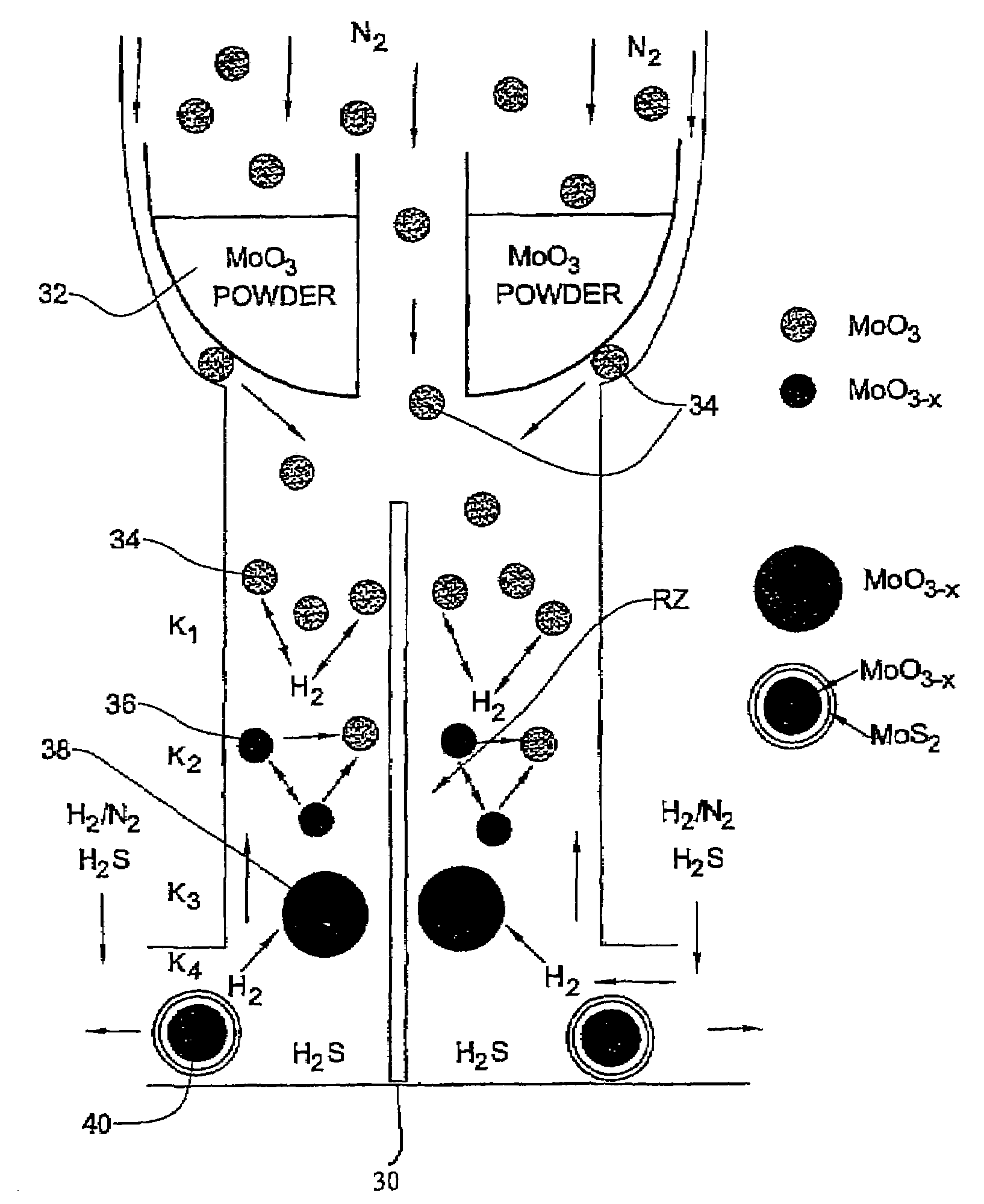
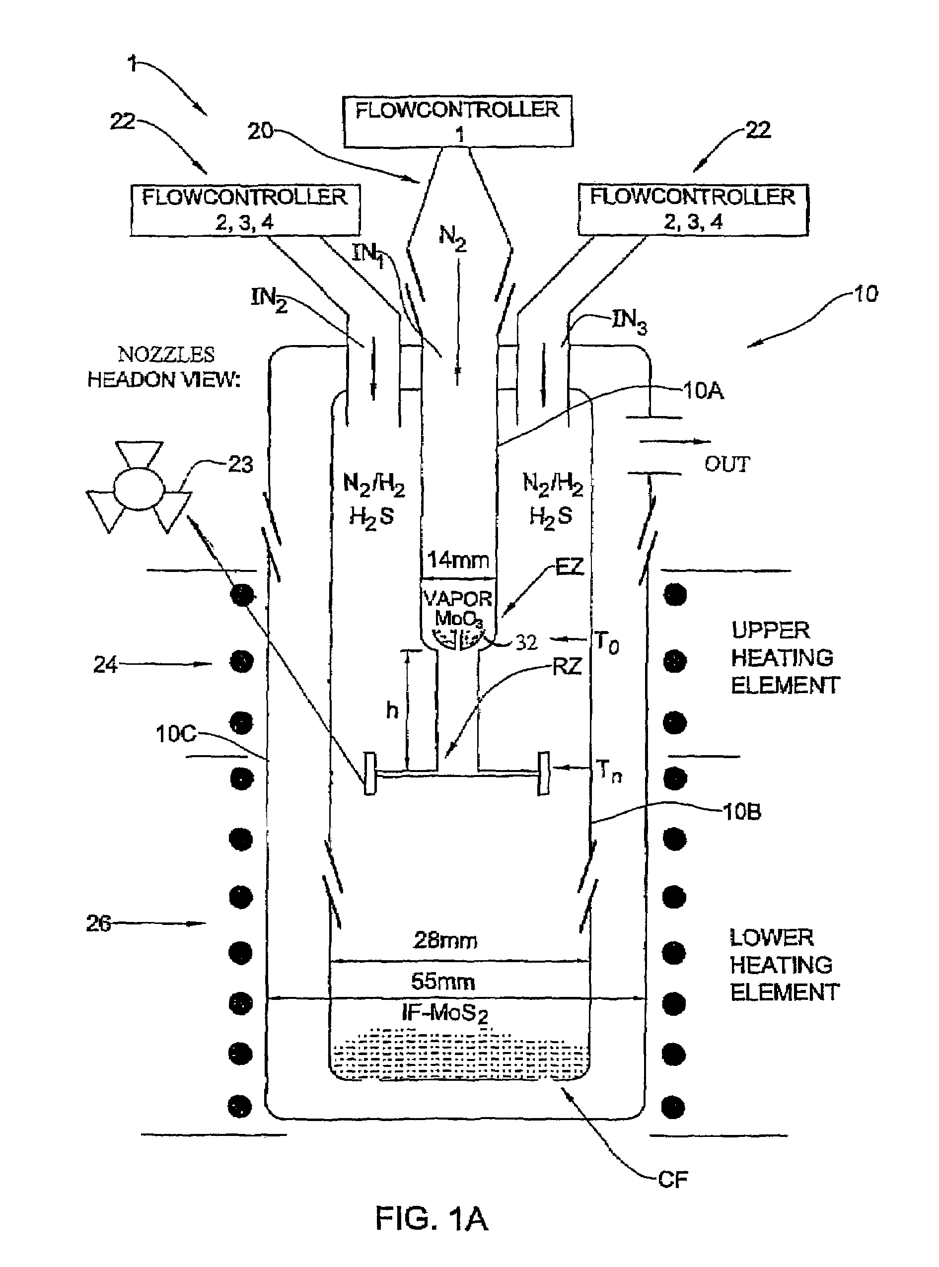
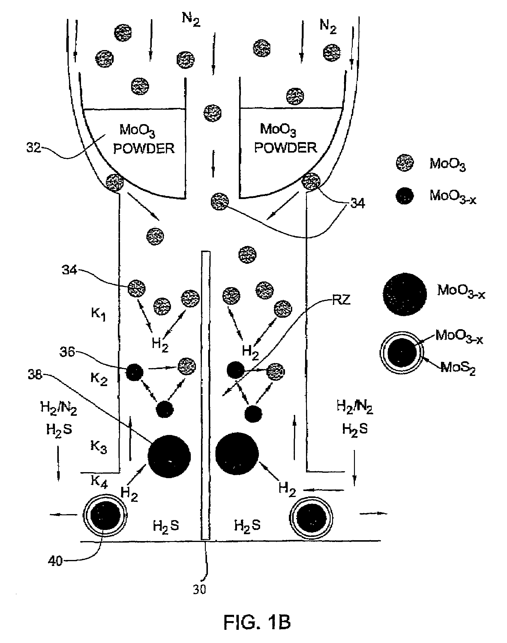
[0092]In the present example, typically 1 g of MoO3 powder was placed in the bucket 32 where the amount of the evaporated powder in each experiment is in the range of 100–105 mg. Such a portion does not influence appreciably the level of the oxide in the bucket. Therefore, the rate of the oxide evaporation from the bucket was time-independent. For a long experiment (that lasts more than 4 hours), the temperature T0 of the bucket 32 has to be increased during the experiment in order to keep the evaporation rate constant.

[0093]The flow rate of N2 (JN2) in the inner tube 10a (i.e., to drive the evaporated metal oxide towards the reacting zone) was controlled by the flow controller 20 (FIG. 1A). The flow of the other gases (H2S, forming gas H2 / N2 and N2) needed for the reactions to occur in the reacting zone RZ were provided by the flow controllers 22. The forming gas was supplied with different flow rates JFG and volume percents CH2 of hydrogen (CH2=1÷8). The H2S concentration (CH2S) w...

example 2

[0153]Reference is made to FIG. 10A illustrating apparatus, generally designate 2, used for production of IF-MoS2 nanostructures. In the apparatus 2, a chemical reactor 50 is differs from reactor 10 of the previously described reactor 1 in several structural elements. The nozzles present in reactor 1 were eliminated. This was done since the nozzles clogged after several hours of reaction. Their elimination permits a longer reaction time resulting in higher yields. However, their elimination requires different control means on the diffusion process. For such a control reactor 50 comprises two additional features, an additional tube 50A and filter 55 (vide infra). Thus, the chemical reactor 50 consists of three concentric quartz tubes: spaced-apart internal tubes 50A and 50B (of, respectively, narrower and higher diameters in the present example), and an external tube 50C.

[0154]The reactor 50 presents a vertical flow line defining an evaporation zone EZ and a reacting zone RZ. The RZ ...

example 3

[0161]FIG. 11 illustrates an apparatus 3 used for production of IF-MoS2 nanostructures. The apparatus 3 comprises a chemical reactor 70 that consists of three concentric quartz tubes 70A, 70B and 70C. The arrangement is such that the interior of tubes 70B and 70C are connected to each other, thereby defining inner tubes 70A and 70B, and external tube 70C. This arrangement is located inside a tube-like housing 70D. The reactor 70 presents a vertical flow line defining a reacting zone RZ starting inside the inner tube 70A at its distal end and extending into tube 70B. The resulting product is collected (precipitates) on a ceramic filter 74 located at the bottom part of the tube 70B. MoO3 powder is maintained in the tube 70A being located within an evaporation zone EZ on an additional filter 73. The reactor 70 is associated with vessels (not shown) containing, respectively, N2 (constituting an inert carrier), H2 / N2 (forming gas-constituting a first reacting agent) and H2S (constituting...


PUM

PropertyMeasurementUnit
Temperatureaaaaaaaaaa
Timeaaaaaaaaaa
Temperatureaaaaaaaaaa

Abstract

A process and apparatus are presented for obtaining inorganic fullerene-like nanostructures. A metal oxide is evaporated at predetermined temperature conditions, and is swept towards a reacting zone, to which first and second gas phase reacting agents are concurrently swept. The evaporated metal oxide thus interacts with the first reacting agent and is converted into metal suboxide nanoparticles in the gas phase. The condensing metal suboxide nanoparticles interact with the second reacting agent in the gas phase resulting in substantially pure phase of the inorganic fullerene-like nanoparticles.

Description

FIELD OF THE INVENTION[0001]This invention relates to a chemical method and apparatus for producing inorganic fullerene-like nanoparticles.BACKGROUND OF THE INVENTION[0002]Inorganic fullerene-like nanoparticles and nanotubes are attractive due to their unique crystallographic morphology and their interesting physical properties. Molybdenum disulfide belongs to a class of solid lubricants useful in vacuum, space and other applications where liquids are impractical to use.[0003]It is known to obtain carbon fullerenes and nanotubes by a synthetic process consisting of condensation of molecular clusters from the vapor phase. This is disclosed for example in the following publication:[0004](1) Dresselhaus, M. S.; Dresselhaus, G.; Eklund, P. C. Science of Fullerenes and Carbon Nanotubes; Academic Press, INC, 1996; pp 1–6, 110–116;[0005](2) Flagen, R. C.; Lunden, M. M. Materials Sc. Eng. A 1995, 204, 113;[0006](3) Deppert, K.; Nielsch, K.; Magnusson, M. H.; Kruis, F. E.; Fissan, H. Nanostr...

Claims


Application Information

Patent Timeline
IPC IPC(8): C01G39/06B82B3/00C01B17/20C01B19/04C01G41/00C01B19/00
CPCB82Y30/00C01B17/20C01B19/007C01G39/06Y10S977/843C01P2004/52C01P2004/62C01P2004/64C01P2004/86C01P2004/04B82B3/00
Inventor TENNE, RESHEFFELDMAN, YISHAYZAK, ALLAROSENTSVEIG, RITA
Owner YEDA RES & DEV CO LTD
Why Eureka
Try Eureka