System and method for management of gas and water in fuel cell system

a fuel cell and process gas technology, applied in the direction of fuel cells, electrical equipment, electrochemical generators, etc., can solve the problems of inadequate humidification levels, difficult to ensure the efficiency of the fuel cell stack under all the possible operating conditions, and dry out, so as to reduce the weight and number of components, the overall system is compact and the effect of high efficiency

Inactive Publication Date: 2006-03-28
HYDROGENICS CORP
View PDF17 Cites 21 Cited by
  • Summary
  • Abstract
  • Description
  • Claims
  • Application Information

AI Technical Summary

Benefits of technology

[0022]The present invention has many advantages over the prior art. The only onboard fluid in the present invention is the coolant. All the water used to humidify the fuel and oxidant is generated by the fuel cell 12 itself. This reduces the weight and number of components in the system, making the overall system compact and highly efficient. The system is capable of rapid response of power demand. All these features are particularly desirable for vehicular applications.

Problems solved by technology

Nonetheless, it is possible for the flow of gas across the cathode side to be sufficient to remove this water, resulting in drying out on the cathode side as well.
All of these requirement are exceedingly demanding and make it difficult to ensure a fuel cell stack will operate efficiently under all the possible range of operating conditions.
While the key issues are ensuring that a fuel cell power unit can always supply a high power level and at a high efficiency and simultaneously ensuring that it has a long life, accurately controlling humidity levels within the fuel cell power unit is necessary to meet these requirements.
Most known techniques of humidification are ill designed to respond to rapidly changing conditions, temperatures and the like.
Many known systems can provide inadequate humidification levels, and may have high thermal inertia and / or large dead volumes, so as to render them incapable of rapid response to changing conditions.
However, this method requires a large number of components and hence reduces the overall efficiency of the fuel cell system.
However, this patent still fails to fully utilize the waste heat and humidity from fuel cell exhaust.

Method used


Image

  • System and method for management of gas and water in fuel cell system
  • System and method for management of gas and water in fuel cell system
  • System and method for management of gas and water in fuel cell system

Examples


first embodiment

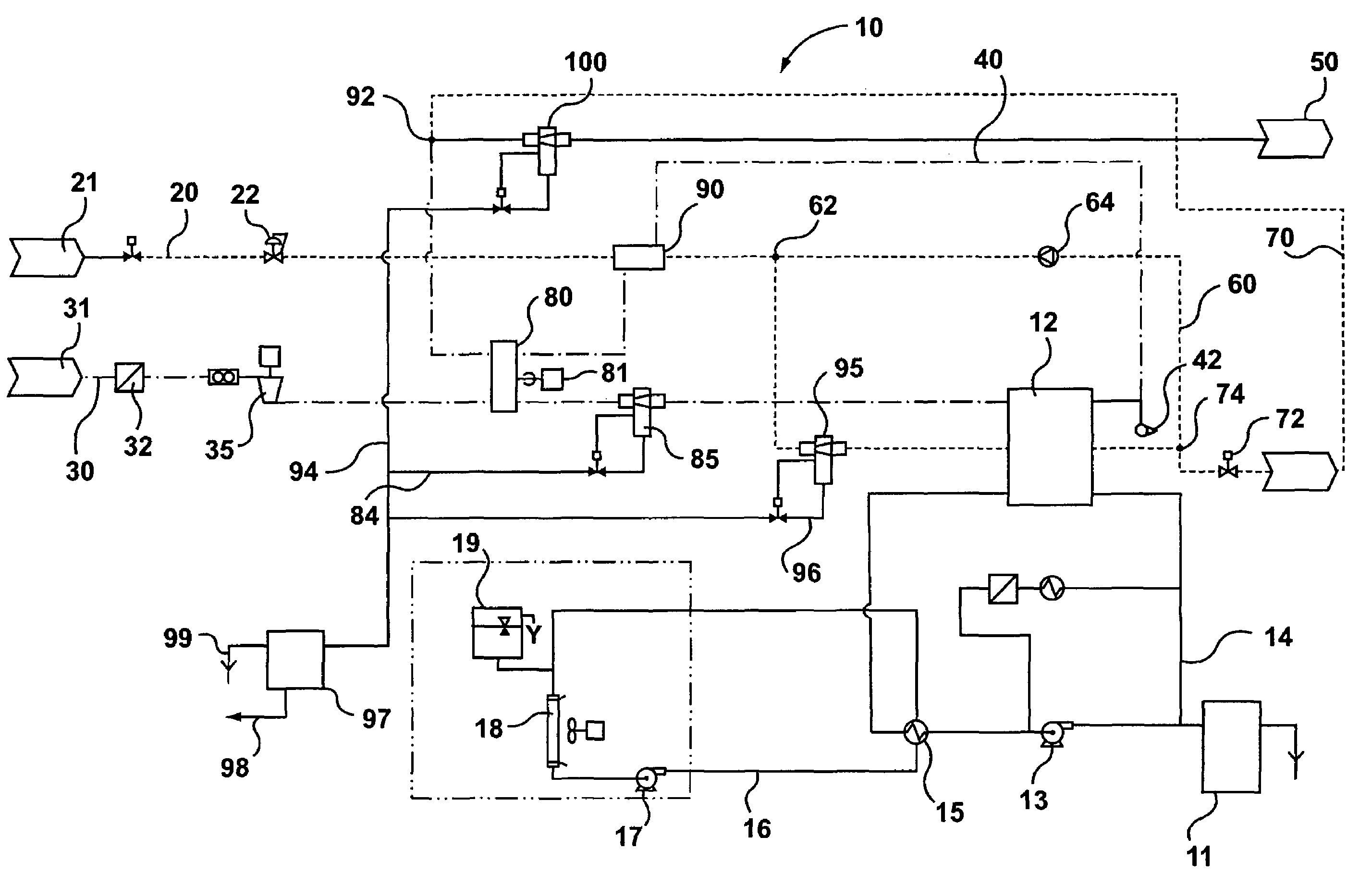
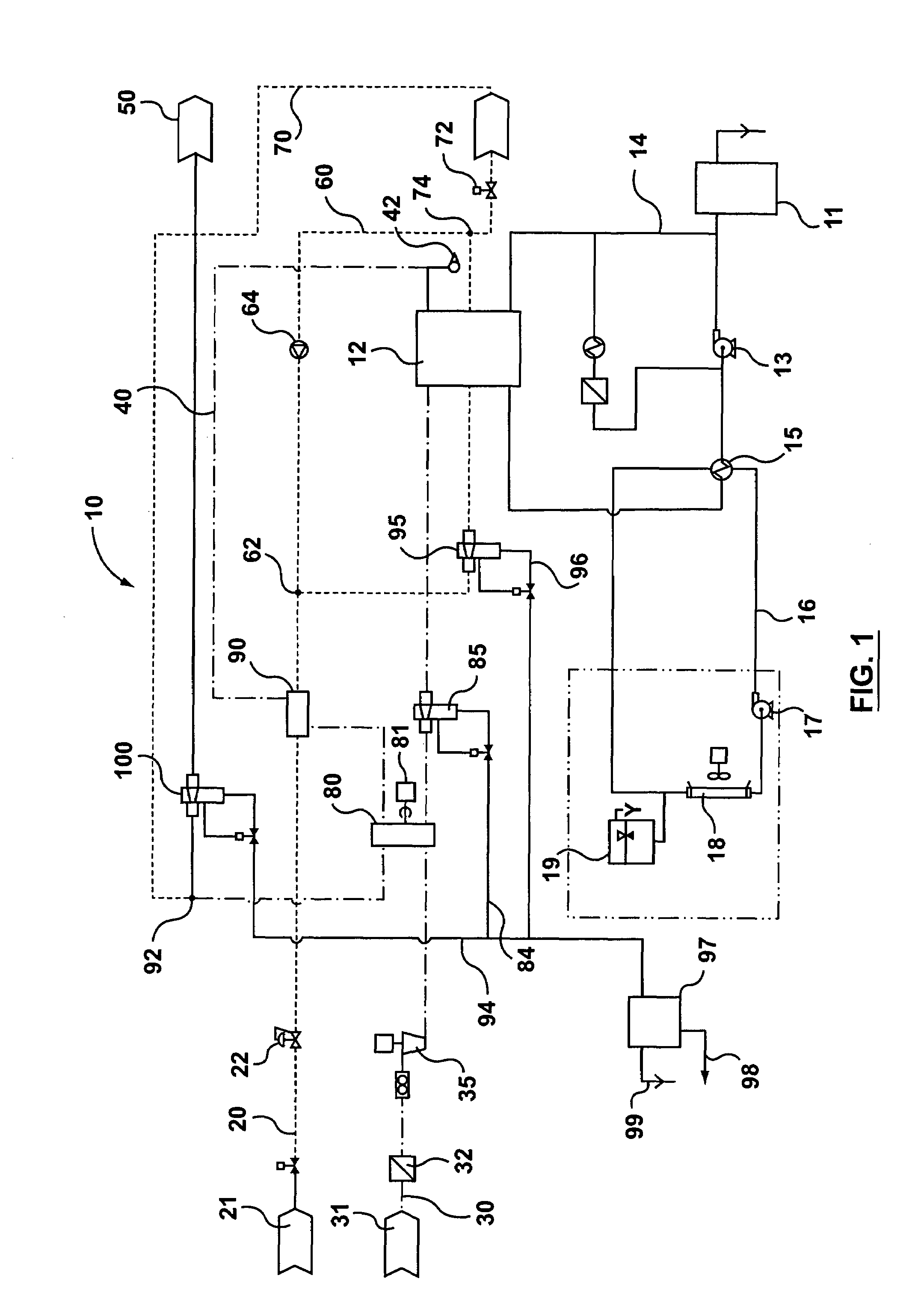
[0027]Referring first to FIG. 1, this shows a schematic flow diagram of a fuel cell gas management system 10 according to the present invention. The fuel cell gas management system 10 comprises a fuel supply line 20, an oxidant supply line 30, a cathode exhaust recirculation line 40 and an anode exhaust recirculation line 60, all connected to a fuel cell 12. It is to be understood that the fuel cell 12 may comprise a plurality of fuel cells or just a single fuel cell. For simplicity, the fuel cell 12 described herein operates on hydrogen as fuel and air as oxidant and can be a Proton Exchange Membrane (PEM) fuel cell. However, the present invention is not limited to this type of fuel cells and applicable to other types of fuel cells.

[0028]The fuel supply line 20 is connected to a fuel source 21 for supplying hydrogen to the anode of the fuel cell 12. A hydrogen humidifier 90 is disposed in the fuel supply line 20 upstream from the fuel cell 12 and an anode water separator 95 is disp...

second embodiment

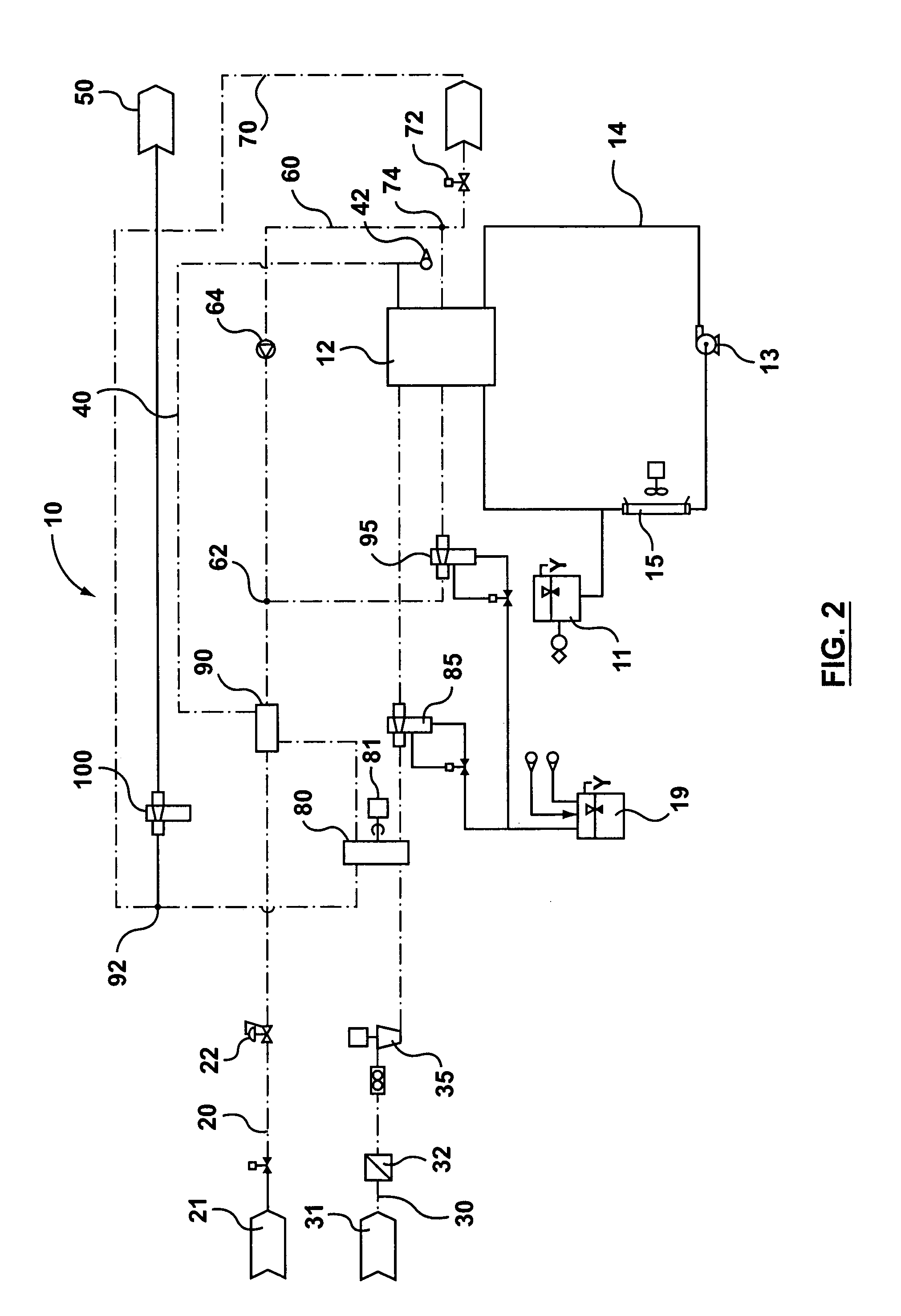
[0047]In the second embodiment, similar components are indicated with same reference numbers, and for simplicity and brevity, the description of those components is not repeated.

[0048]In this second embodiment, a high pressure compressor 105 is provided in the oxidant supply line 30 upstream from the enthalpy wheel 80 to pressurize the incoming air from the air filter 32. An after cooler heat exchanger 110 is provided between the compressor 105 and the enthalpy wheel 80 to cool the compressed air having an elevated temperature. Hence, in addition to the cooling loop 14 for the fuel cell 12, an additional cooling loop 114 is provided including a water-water heat exchanger 110 and a coolant tank 111. The cooling loop 114 may also run through the compressor motor 106, compressor motor controller 107 and other power switching board 108 for the compressor 105. The coolant in both cooling loops 14 and 114 is driven by the pump 13. A heat exchanger 108 can be provided in the loop 114 for c...


PUM

PropertyMeasurementUnit
flow rateaaaaaaaaaa
enthalpyaaaaaaaaaa
heataaaaaaaaaa

Abstract

A fuel cell system has: a fuel cell having a first reactant inlet, a first reactant outlet, a second reactant inlet, a second reactant outlet, and optionally a coolant inlet and coolant outlet. A first reactant supply subsystem supplies a first reactant incoming stream to the first reactant inlet of the fuel cell. A second reactant supply subsystem supplies a second reactant incoming stream to the second reactant inlet of the fuel cell. A first reactant recirculation subsystem recirculates at least a portion of the first reactant exhaust stream from the first reactant outlet to an enthalpy shifting subsystem in which one portion of the heat and moisture in first reactant exhaust stream is transferred to one of the first reactant incoming stream in the first reactant supply subsystem and the second reactant incoming stream in the second reactant supply subsystem. Another portion of the heat and moisture is transferred to the other stream. A method of controlling reactant and water in a fuel cell system is also disclosed.

Description

FIELD OF THE INVENTION[0001]The present invention relates generally to an apparatus and method for management of process gases for a fuel cell system. More particularly, the present invention relates to an apparatus and method for controlling the humidity, temperature and flow of fuel cell process gases.BACKGROUND OF THE INVENTION[0002]Fuel cell systems are seen as a promising alternative to traditional power generation technologies due to their low emissions, high efficiency and ease of operation. Fuel cells operate to convert chemical energy into electrical energy. Proton exchange membrane fuel cells comprise an anode, a cathode, and a selective electrolytic membrane disposed between the two electrodes. In a catalyzed reaction, a fuel such as hydrogen, is oxidized at the anode to form cations (protons) and electrons. The ion exchange membrane facilitates the migration of protons from the anode to the cathode. The electrons cannot pass through the membrane and are forced to flow th...

Claims


Application Information

Patent Timeline
Patent Type & Authority Patents(United States)
IPC IPC(8): H01M8/04
CPCH01M8/04014H01M8/04119H01M8/04097Y02E60/50
Inventor CARGNELLI, JOSEPHSIMPSON, TODD A.DEL CORE, ROBERT C.BURANY, STEPHENYE, JIANMINGBAZZARELLA, RICARDO
Owner HYDROGENICS CORP
Why Eureka
Try Eureka