Digital envelope detector

a detector and digital technology, applied in the direction of instruments, measurement using digital techniques, measurement arrangements for variables, etc., can solve the problems of limited measurement accuracy, limited accuracy of measurement, and first method which employs a diode detector circuit, and achieves efficient and accurate measurement of the envelope of an ac signal.

Inactive Publication Date: 2006-03-28
THE UNITED STATES OF AMERICA AS REPRESENTED BY THE SECRETARY OF THE NAVY
View PDF18 Cites 7 Cited by
  • Summary
  • Abstract
  • Description
  • Claims
  • Application Information

AI Technical Summary

Benefits of technology

[0008]It is an object of the present invention to provide a method for the efficient and accurate measurement of the envelope of an AC signal.
[0009]It is also an object of the present invention to provide a system which facilitates the accurate measurement of the peak amplitudes of an AC signal as a function of time and thus determine the envelope of the signal.
[0010]It is a further object to provide a means by which the decay response of an AC signal can be efficiently and accurately measured and recorded.
[0012]It is a further object to provide a device which provides the highest possible resolution in mechanical loss data in order to provide the highest sensitivity and selectivity from resonator based sensors.

Problems solved by technology

The first method which employs a diode detector circuit is limited in its accuracy because of the response characteristics of the RC circuit.
Since the RC interaction includes a relatively substantial time delay, necessary for the charging and discharging of the capacitor the accuracy of the measurement is limited.
The second method, digitizing of the wave form, require substantial amounts of numerical manipulation of the data and requires a multitude of mathematical operations.
This method also requires performing a mathematical “fit” which introduces error into the envelope measurement.
The third method is simply slow and inaccurate because it requires an operator to visually plot the decay response of the signal.

Method used


Image

  • Digital envelope detector
  • Digital envelope detector
  • Digital envelope detector

Examples


Embodiment Construction

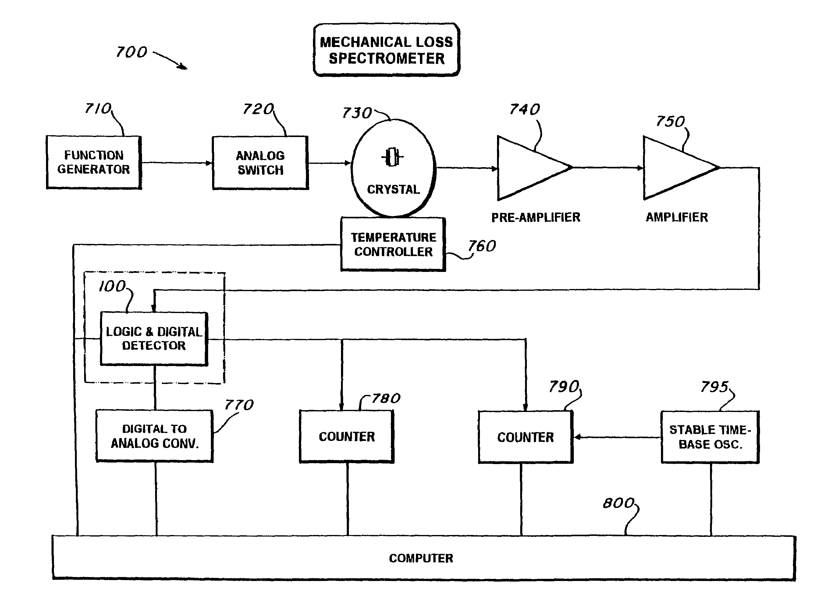
[0024]The disclosed system enables the user to measure peak amplitudes of an electrical signal as a function of time both rapidly and with high precision. The system in its preferred embodiment comprises the disclosed envelope detector device, a CPU, and accompanying software which together are integrated into a system capable of making very accurate envelope measurements.

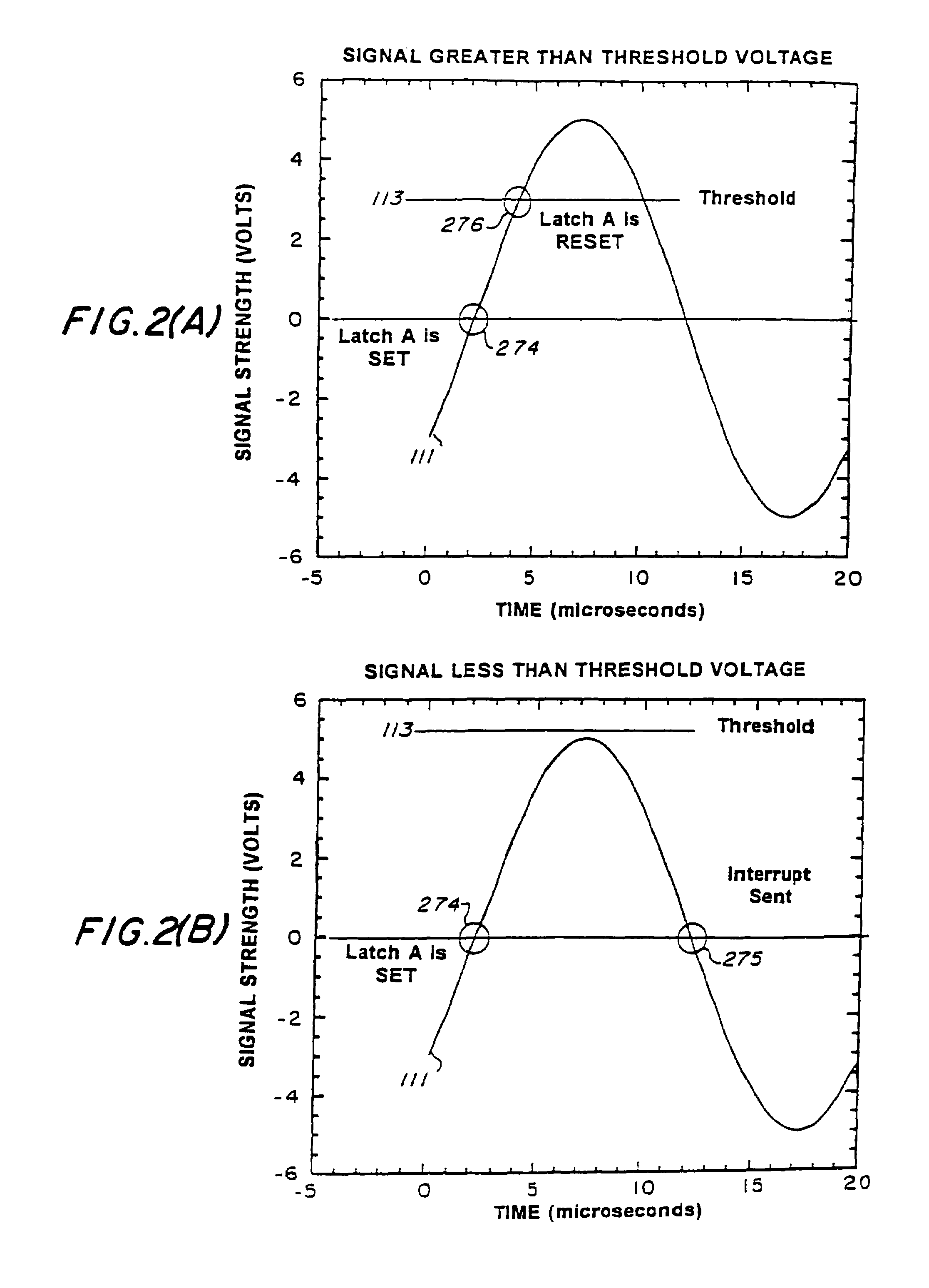
[0025]In brief, the basic concept this system employs is as follows. A multitude of reference points or threshold voltages are selected by the user or CPU. While the disclosed system is described by explaining its operation when it is applied to obtain the envelope of a monotonically decreasing signal, the technique is not limited to this particular application.

[0026]If the method is applied to obtain the envelope of a decaying sinusoidal signal the output is an array of numbers, cycles and peak amplitudes. The threshold voltages are selected from a range within the maximum amplitude of the oscillating sample. The ...


PUM


Abstract

A digital envelope detector (consisting of both hardware and software) that provides accurate measurements of changes of peak values of an AC signal (these peak values constitute the envelope of a signal). Such accurate envelope measurements are required, e.g., to optimize the accuracy and selectivity of chemical sensors. The envelope values required for these sensors can not be obtained with common instruments (e.g. voltmeters) since these meters require that successive peaks be the same amplitude. Therefore, they can not measure the envelope of a gradually increasing or decreasing AC signal from the chemical sensors. The only possible alternative to this invention is high speed, high resolution analog-to-digital conversion (ADC) followed by extensive statistical analysis. The ADC method is much more expensive, slower, and excessively complicated compared to the invention. The invention works as follows: A signal of interest is compared to each of a set of accurately calibrated reference (or threshold) voltages provided by a digital to analog converter. A digital logic circuit and software respond each time the signal fails to exceed the current reference voltage. In that event, relevant data (e.g. time or cycle count) are digitally recorded and a new reference voltage is installed. The process is repeated until the desired range of change of the signal is measured. The result is a set of amplitudes as a function of time and / or cycle that fully and accurately describe the desired portion of a signal envelope.

Description

[0001]The present application is a continuation of application Ser. No. 10 / 254,803, filed on now Sep. 26, 2002 now U.S. Pat. No. 6,806,721, which is a divisional of application Ser. No. 09 / 602,659 filed Jun. 28, 2000, now U.S. Pat. No. 6,462,559, which is a divisional of application Ser. No. 08 / 866,310, filed on May 30, 1997, now abandoned.BACKGROUND OF THE INVENTION[0002]The present invention relates in general to the detection of the peak values of an AC signal and in specific to the detection and measurement of the response envelope of an AC signal as a function of time both rapidly and with high precision.[0003]Prior methods of obtaining the envelope of an electrical signal rely upon: 1) the use of diode detector circuits incorporating an RC time constant; 2) digitizing the wave form of the signal and performing a mathematical fit to determine each peak value or 3) making measurement directly from an oscilloscope trace.[0004]The first method which employs a diode detector circui...

Claims


Application Information

Patent Timeline
Patent Type & Authority Patents(United States)
IPC IPC(8): G01R23/00G01D1/18G06F15/00G01R19/25
CPCG01R19/2506
Inventor KANT, RICHARD A.
Owner THE UNITED STATES OF AMERICA AS REPRESENTED BY THE SECRETARY OF THE NAVY
Why Eureka
Try Eureka