Planar antenna with supplemental antenna current configuration arranged between dominant current paths

a technology of supplemental antenna current and dominant current path, applied in the direction of antenna feed intermediates, resonance antennas, radiating element structural forms, etc., can solve the problems of leaking energy into the substrate, and affecting the reception efficiency

Inactive Publication Date: 2006-03-28
UNIV OF COLORADO THE REGENTS OF
View PDF6 Cites 232 Cited by
  • Summary
  • Abstract
  • Description
  • Claims
  • Application Information

AI Technical Summary

Benefits of technology

[0015]As will be described in more detail hereinafter, there is disclosed herein an antenna arrangement and associated method in which a pair of at least generally planar opposing antenna arms each supports a first high frequency antenna current that is produced responsive to an input. Each of the arms includes a peripheral outline for confining the first high frequency current to a pair of first and second dominant paths, that are defined by the peripheral outline, in a spaced apart relationship across each of the opposing antenna arms so as to define an area ...

Problems solved by technology

The high dielectric constants of familiar substrates such as, for example, silicon, act in an adverse manner by degrading the efficiency of reception, or in other words, “gain”, of a signal arriving at the antenna from a direction opposite the substrate.
Generally, antenna currents induced from air-side radiation create high electric fields within such a high permittivity substrate, which, in turn, cause a leakage of energy into the substrate, partly in the form of surface wave modes.
Further, surface waves induced by discontinuities in the substrate and traveling along the plane of the antenna, interfere with expected antenna reception.
Unfortunately, however, at 10 μm wavelengths and below, planar antennas are themselves only several microns in length.
Accordingly, attachment of such lens components is submitted to necessitate additional fabrication steps, which may well prove to be tedious and expensive.
For applications where ...

Method used


Image

  • Planar antenna with supplemental antenna current configuration arranged between dominant current paths
  • Planar antenna with supplemental antenna current configuration arranged between dominant current paths
  • Planar antenna with supplemental antenna current configuration arranged between dominant current paths

Examples


Embodiment Construction

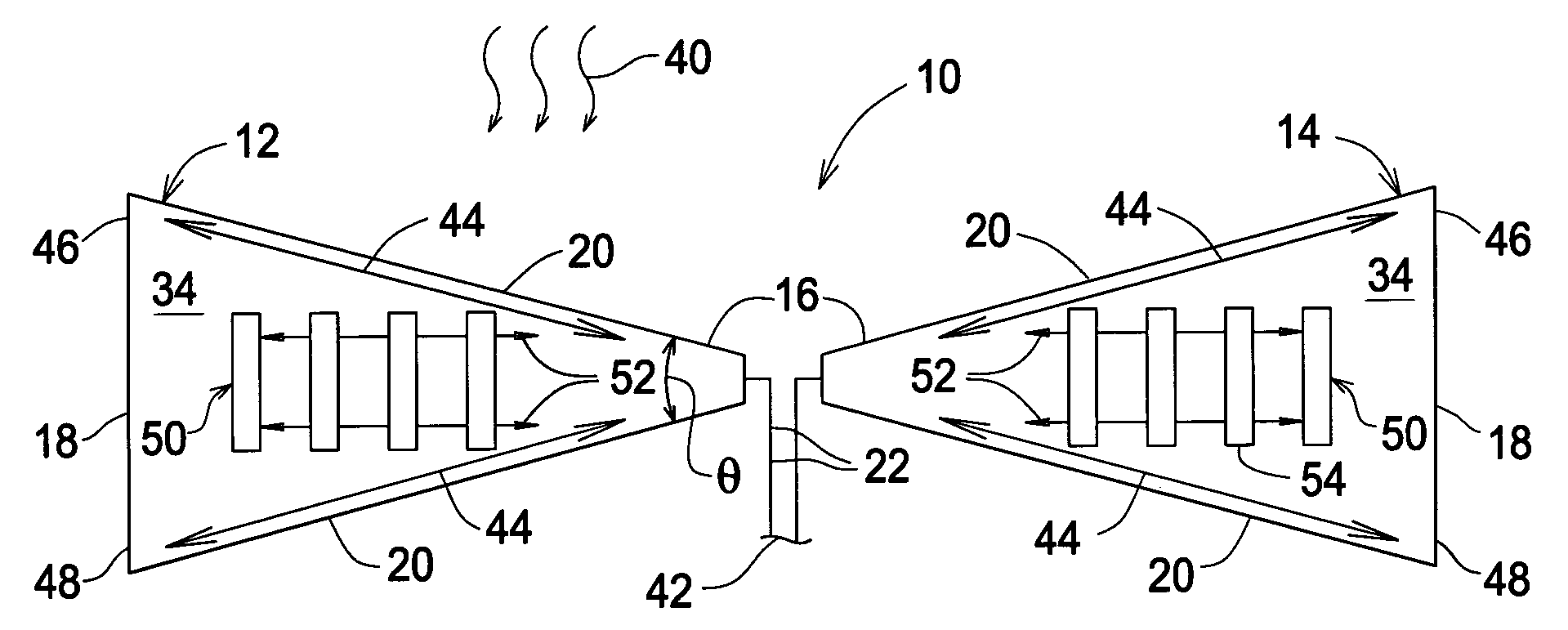
[0033]Turning now to the figures, wherein like reference numbers are used to refer to like components, attention is immediately directed to FIG. 1 which illustrates one implementation of a planar antenna produced in accordance with the present invention and generally indicated by the reference numeral 10. It is noted that the various figures are not to scale for purposes of enhancing the reader's understanding. Moreover, descriptive terminology such as upper, lower, vertical and horizontal is in no way intended as limiting with respect to device orientation or operation as is used only for the purpose of providing a detailed understanding.

[0034]In the present example, planar antenna 10 includes a peripheral outline that is in the form of a bow-tie which is defined by an opposing pair of first and second bow arms 12 and 14, respectively. Each bow arm includes an innermost apex end 16 and an outermost edge 18. A pair of outwardly diverging edges 20 extend between apex end 16 and outer...


PUM


Abstract

An antenna arrangement is described in which a pair of at least generally planar opposing antenna arms each support a first high frequency antenna current responsive to an input. Each arm includes a peripheral outline for confining the first high frequency current to a pair of first and second dominant paths, that are defined by the peripheral outline, in a spaced apart relationship across each of the opposing antenna arms so as to define an isolated area between the first and second paths. A configuration is located in this area of at least one of the antenna arms for producing an additional high frequency current responsive to the input. The additional high frequency current cooperates with the first high frequency antenna current to produce an overall antenna response. In one feature, the opposing antenna arms are bow arms which cooperate to define an overall bow-tie configuration as the peripheral outline.

Description

BACKGROUND OF THE INVENTION[0001]The present invention relates generally to planar antennas and, more particularly, to a planar antenna arrangement defining at least one pair of dominant paths carrying antenna currents and having a configuration disposed therebetween for producing additional antenna currents. The planar antenna of the present invention is advantageously implemented in a bow-tie configuration.[0002]Planar antennas are used at microwave, millimeter wave, and infrared frequencies to couple energy between free space and a wire circuit. The planar configuration of these antennas enables ease of fabrication using electrically conductive layers formed on non-electrically conductive substrate materials. The antenna itself includes the electrically conductive layer sitting atop the substrate layer which, of course, exhibits a dielectric constant (defined as permittivity relative to the permittivity of free space). The high dielectric constants of familiar substrates such as,...

Claims


Application Information

Patent Timeline
IPC IPC(8): H01Q13/10H01Q9/28
CPCH01Q9/285
Inventor WEISS, MANOJA D.
Owner UNIV OF COLORADO THE REGENTS OF
Why Eureka
Try Eureka