Dynamic optical filter having a spatial light modulator
What is Al technical title?
Al technical title is built by PatSnap Al team. It summarizes the technical point description of the patent document.
a spatial light modulator and optical filter technology, applied in the field of optical filters, can solve the problem that the dgefs are not wavelength plan independent, and achieve the effect of allowing attenuation or filtering of the optical signal
Inactive Publication Date: 2006-03-28
II VI DELAWARE INC
View PDF33 Cites 44 Cited by
Summary
Abstract
Description
Claims
Application Information
AI Technical Summary
This helps you quickly interpret patents by identifying the three key elements:
Problems solved by technology
Method used
Benefits of technology
[0007]An object of the present invention is to provide a dynamic optical filter, such as a DGEF, having a spatial light modulator, wherein the spatial light modulator pixelates th
Problems solved by technology
Further, these DGEFs are not
Method used
Image
Click on the blue label to locate the original text in one second.
Reading with bidirectional positioning of images and text.
Examples
Embodiment Construction
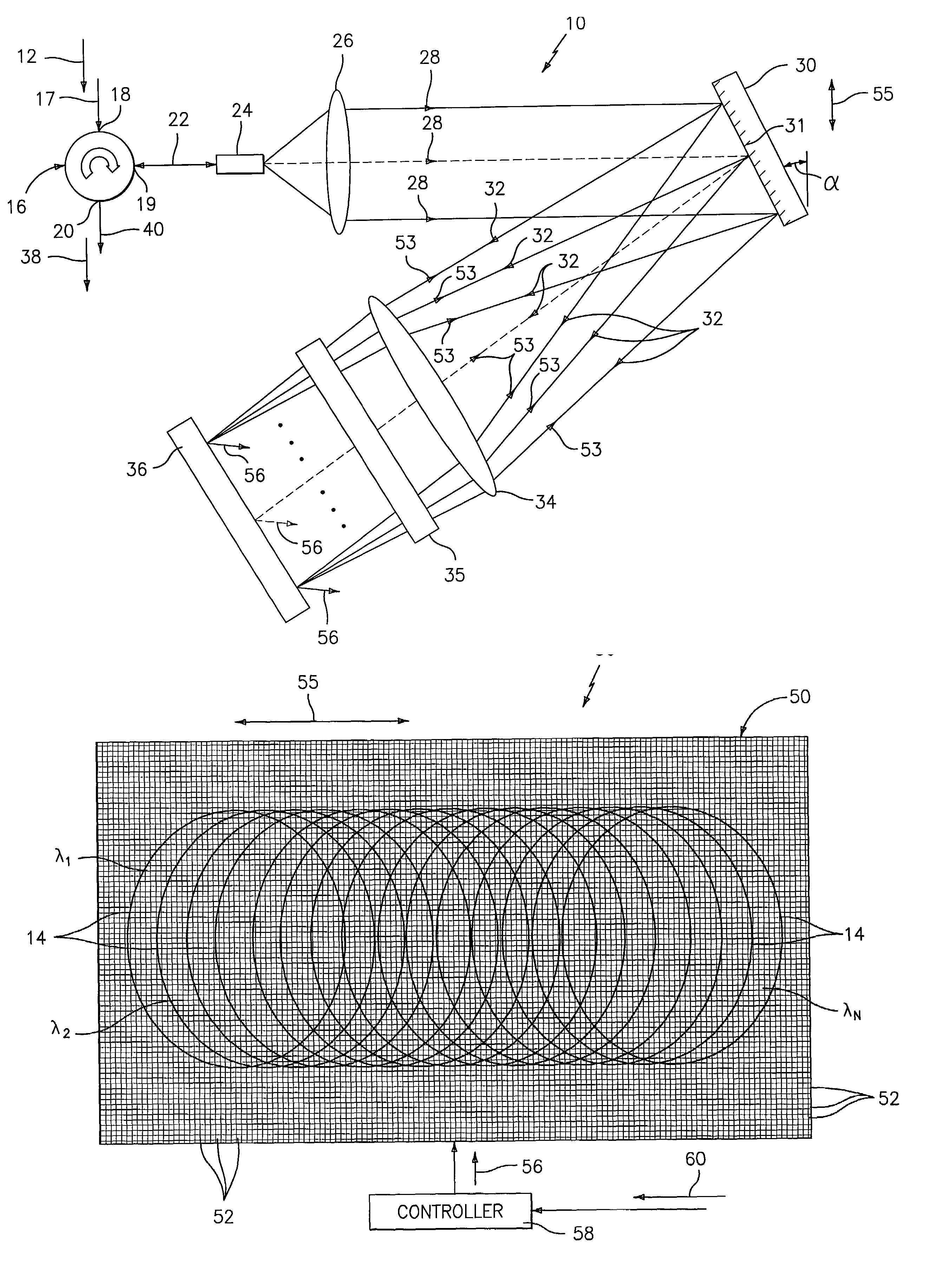
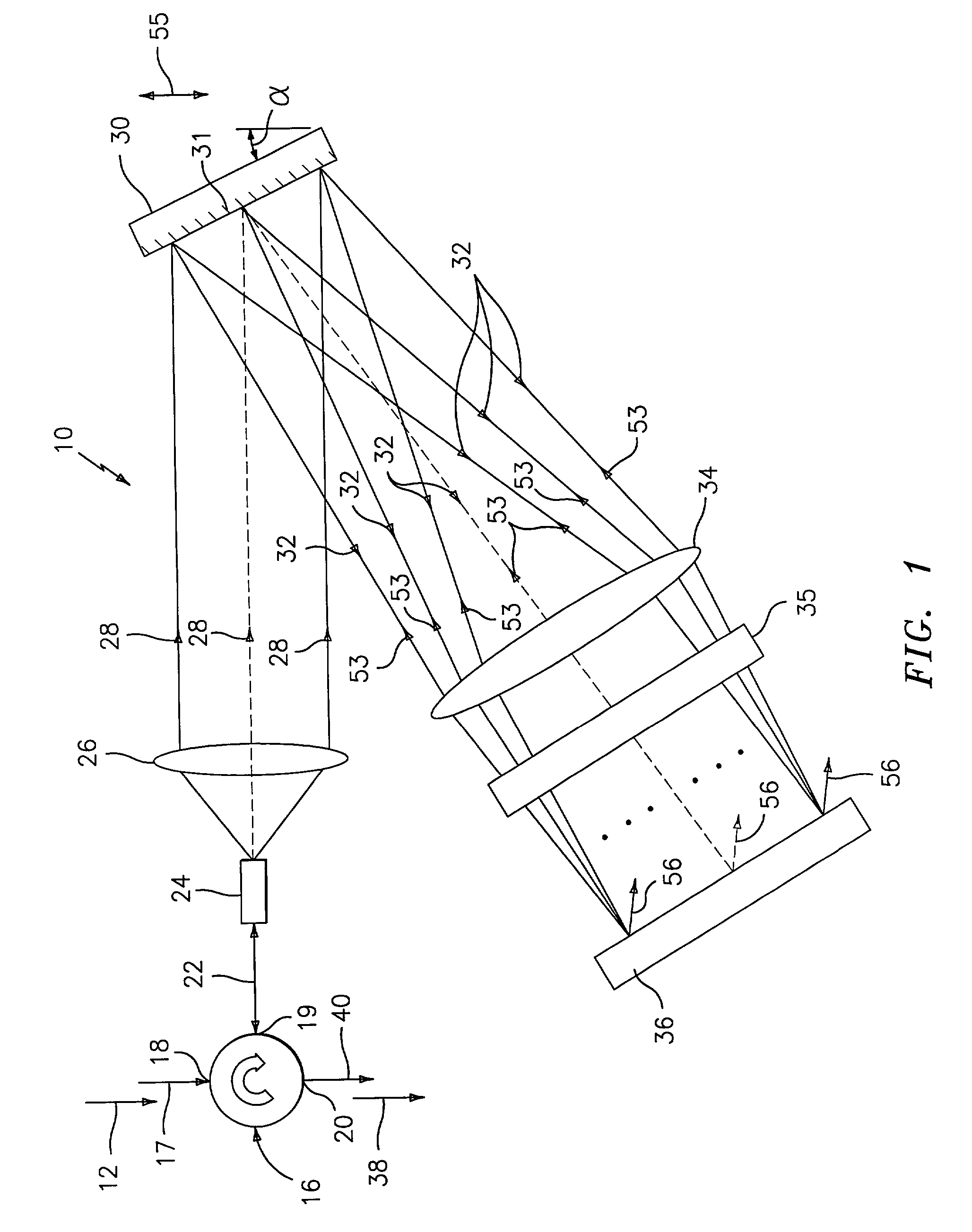
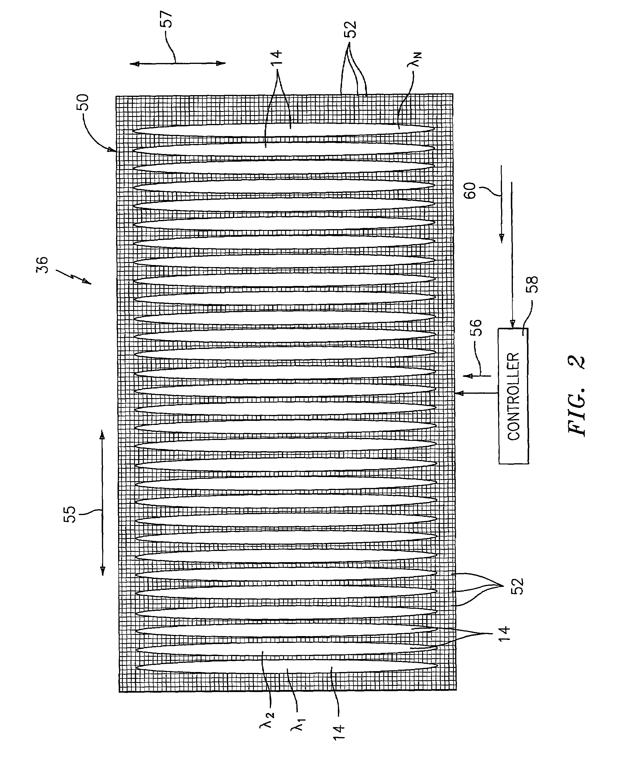
[0101]As shown in FIGS. 1 and 2, an optical filter, generally shown as 10, selectively attenuates or filters a wavelength band(s) of light (i.e., optical channel(s)) or a group(s) of wavelength bands of an optical WDM input signal 12. Each of the optical channels 14 (see FIG. 2) of the input signal 12 is centered at a respective channel wavelength (λ1,λ2,λ3, . . . λN). The optical filter is controllable or programmable to selectively provide a desired filter function, which will be described in greater detail hereinafter. For example, the optical filter may function as a dynamic gain equalization filter (DGEF) (or dynamic spectral equalizer (DSE)) that selectively attenuates an optical channel or group of optical channels of the optical WDM input signal 12 to equalize the power or gain of the output signal over its spectrum. To simply the description of the optical filter 10 embodying the present invention, the following description of the optical filter will be described as a DGEF....
PUM
Abstract
An dynamic optical filter 10 is provided to selectively attenuate or filter a wavelength band(s) of light (i.e., optical channel(s)) or a group(s) of wavelength bands of an optical WDM input signal 12. The optical filter is controllable or programmable to selectively provide a desired filter function. The optical filter 10 includes a spatial light modulator 36, which comprises an array of micromirrors 52 that effectively forms a two-dimensional diffraction grating mounted in a retro-reflecting configuration. Each optical channel 14 is dispersed separately or overlappingly onto the array of micro-mirrors 52 along a spectral axis or direction 55 such that each optical channel or group of optical channels are spread over a plurality of micromirrors to effectively pixelate each of the optical channels or input signal. Each channel 14 or group of channels may be selectively attenuated by flipping or tilting a selected number of micromirrors to thereby deflect a portion of the incident radiation away from the return optical path. The micro-mirrors operate in a digital manner by flipping between a first and second position in response to a control signal 56 provided by a controller 58 in accordance with an attenuation algorithm and an input command 60. The switching algorithm may provide a bit (or pixel) map or look-up table indicative of the state of each of the micro-mirrors 52 of the array to selectively attenuate the input signal and provide a modified output signal 38 at optical fiber 40.
Description
CROSS REFERENCES TO RELATED APPLICATIONS[0001]This application claims the benefit of U.S. Provisional Application No. 60 / 281,079, filed Apr. 3, 2001; U.S. Provisional Application No. 60 / 311,002, filed Aug. 8, 2001; U.S. Provisional Application No. 60 / 332,319, filed Nov. 16, 2001; U.S. Provisional Application No. 60 / 365,741, filed Mar. 18, 2002; U.S. Provisional Application No. 60 / 365,461, filed Mar. 18, 2002; and U.S. patent application Ser. No. 10 / 120,617, filed Apr. 11, 2002, all of which are incorporated herein by reference in their entirety.TECHNICAL FIELD[0002]The present invention relates to optical filters, and more particularly to dynamic optical filter, such as dynamic gain equalization filters (DGEFs), including a spatial light modulator, such as an array of micro-mirrors to selectively attenuate a wavelength division multiplexed (WDM) optical signal.BACKGROUND ART[0003]MEMS micro-mirrors have been widely explored and used for optical switching and attenuation applications...
Claims
Application Information
Patent Timeline
Application Date:The date an application was filed.
Publication Date:The date a patent or application was officially published.
First Publication Date:The earliest publication date of a patent with the same application number.
Issue Date:Publication date of the patent grant document.
PCT Entry Date:The Entry date of PCT National Phase.
Estimated Expiry Date:The statutory expiry date of a patent right according to the Patent Law, and it is the longest term of protection that the patent right can achieve without the termination of the patent right due to other reasons(Term extension factor has been taken into account ).
Invalid Date:Actual expiry date is based on effective date or publication date of legal transaction data of invalid patent.