Rectifying circuit

Active Publication Date: 2006-03-28
DENSO CORP
View PDF15 Cites 11 Cited by
  • Summary
  • Abstract
  • Description
  • Claims
  • Application Information

AI Technical Summary

Benefits of technology

[0007]According, it is an object of the present invention to provide a rectifying circuit, which is capable of balancing the decrease of the breakdown voltage of its rectifying diode with keeping the whole structure of the rectifying circuit simple and compact.

Problems solved by technology

This method, however, may cause the forward loss of the rectifying diode and the radiated noise for the reverse recovery time thereof, whereby to reduce the breakdown voltage of the rectifying diode as much as possible while keeping it within the allowed limits.
Adding the snubber circuit to the rectifying circuit causes its whole structure to be large-sized and its cost to increase.

Method used


Image

  • Rectifying circuit
  • Rectifying circuit
  • Rectifying circuit

Examples


first embodiment

[0019](First Embodiment)

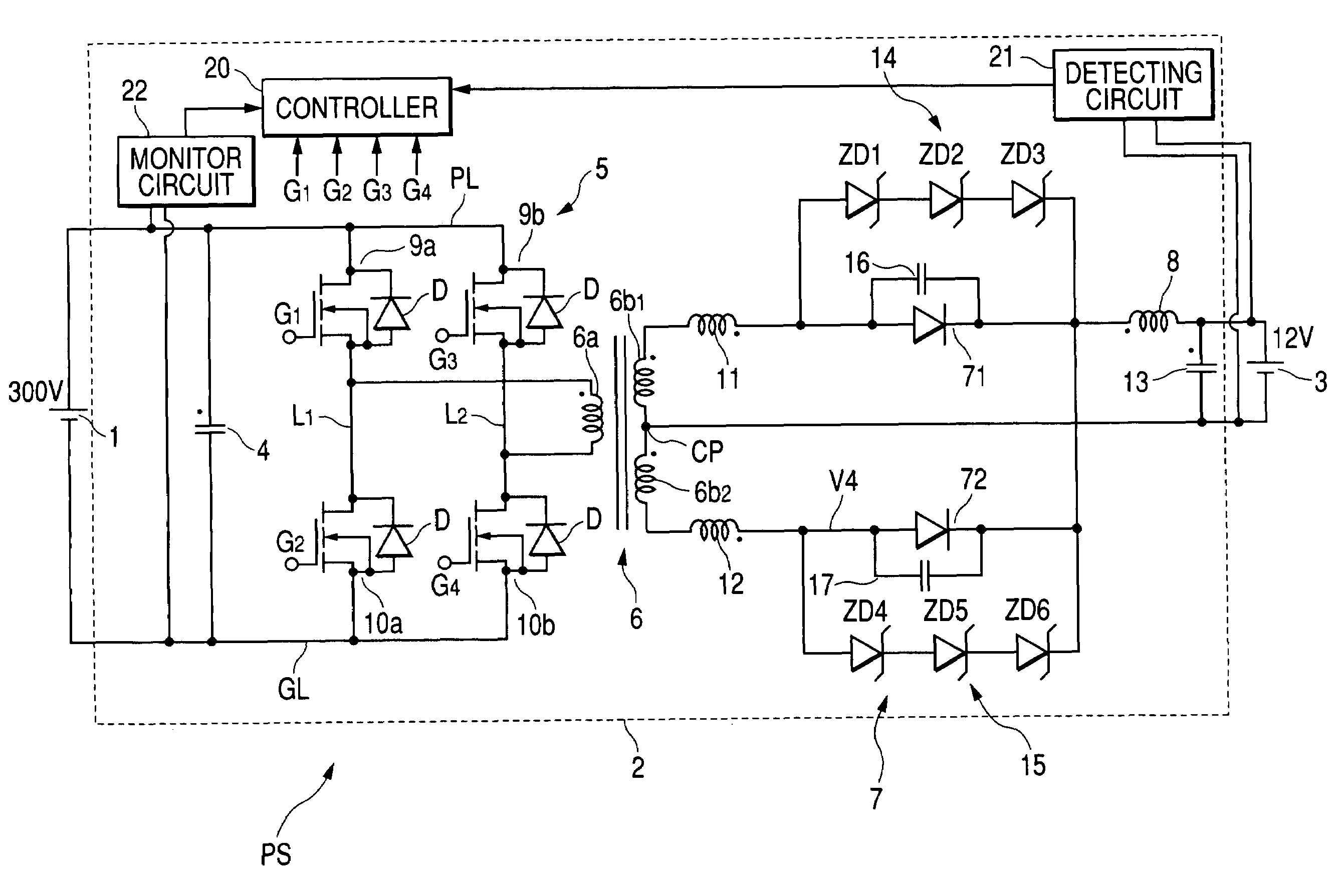
[0020]FIG. 1 is a diagram illustrating a circuit structure of a power supply PS for vehicles, in which a DC—DC converter including a rectifying circuit according to a first embodiment of the present invention.

[0021]The power supply PS is provided with a high DC-voltage battery 1, such as 300V battery, a DC—DC converter 2 electrically connected thereto, and a low DC-voltage battery 3, such as 12V battery, which is electrically connected to the DC—DC converter 2.

[0022]For example, the high DC-voltage battery 1 is a high DC-voltage battery for traction units installed in the vehicle, and the low DC-voltage battery 3 is a low DC-voltage battery for auxiliary loads installed in the vehicle.

[0023]The DC—DC converter 2 includes an input-side smoothing capacitor 4, an inverter circuit 5, a step-down transformer 6, a rectifying circuit 7, a smoothing inductor 8, and an output-side smoothing capacitor 13.

[0024]The input-side smoothing capacitor 4 is electrically connec...

second embodiment

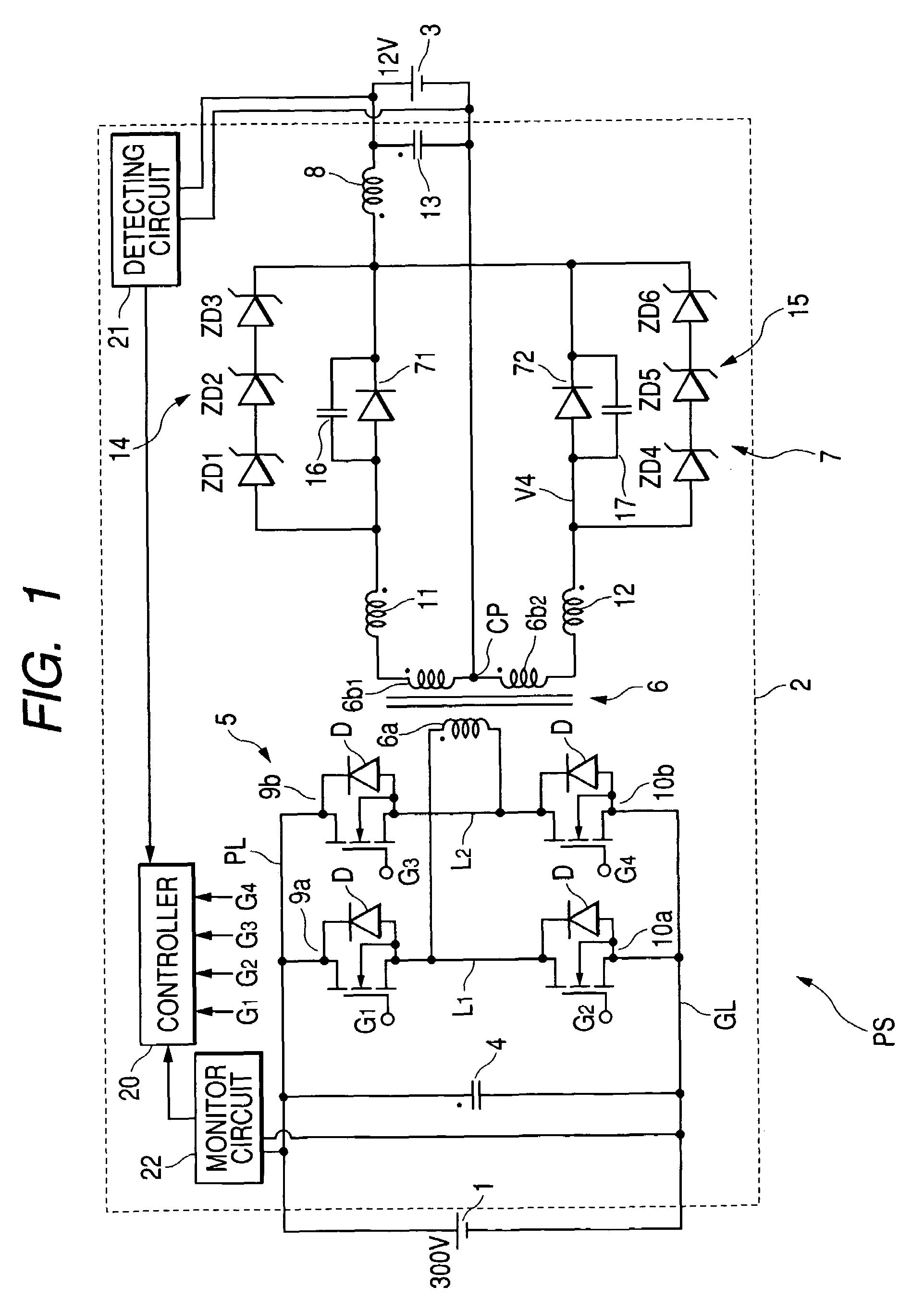
[0067](Second Embodiment)

[0068]FIG. 2 is a circuit diagram illustrating a circuit structure of a power supply PSa for vehicles, in which a DC—DC converter including a rectifying circuit according to a second embodiment of the present invention.

[0069]Incidentally, elements of the DC—DC converter according to the third embodiment, which are substantially identical with those of the power supply PS according to the first embodiment, are assigned to the same reference characteristics of the power supply PS shown in FIG. 1, and explanations thereabout are omitted or simplified. That is, specific points of the power supply PSa according to the second embodiment different from the power supply PS according to the first embodiment are focused.

[0070]As shown in FIG. 2, the power supply PSa includes a DC—DC converter 2a, and the DC—DC converter 2a is composed of a rectifying circuit 7a.

[0071]The rectifying circuit 7a, in place of the protection diode circuits 14 and 15, is composed of protec...

third embodiment

[0082](Third Embodiment)

[0083]FIG. 3 is a circuit diagram illustrating a circuit structure of a power supply PSb for vehicles, in which a DC—DC converter including a rectifying circuit according to a third embodiment of the present invention.

[0084]Incidentally, elements of the DC—DC converter according to the third embodiment, which are substantiality identical with those of the power supply PS according to the first embodiment, are assigned to the same reference characteristics of the power supply PS shown in FIG. 1, and explanations thereabout are omitted or simplified. That is, specific points of the power supply PSb according to the third embodiment different from the power supply PS according to the first embodiment are focused.

[0085]As shown in FIG. 3, the power supply PSb includes a DC—DC converter 2b, and the DC—DC converter 2b is composed of a rectifying circuit 7b.

[0086]The rectifying circuit 7b, in place of the rectifying diodes 71 and 72, is composed of synchronous rect...


PUM


Abstract

In a rectifying circuit, a rectifying diode is configured to rectify a first AC voltage to output a first DC voltage. A protection diode circuit has constant reverse voltage diodes and electrically connected to the rectifying diode in parallel thereto. The constant reverse voltage diodes are electrically connected to each other in series. Each of the constant reverse voltage diodes has a breakdown voltage and a second forward voltage. A sum of the breakdown voltages of the constant reverse voltage diodes is lower than the breakdown voltage of the rectifying diode, and a sum of said second forward voltages is higher than the first forward voltage of the rectifying diode.

Description

BACKGROUND OF THE INVENTION[0001]The present invention relates to a rectifying circuit, and more particularly, to a rectifying circuit used in a DC(direct current)-DC converter for delivering power between two batteries which have different rated DC voltages, respectively.[0002]Rectifying circuits each having a rectifying diode are applied for DC—DC converters. In cases where the rectifying diode turns off, the sum of reverse bias voltage inputted to the rectifying diode and the reverse recovery voltage are applied on the rectifying diode. This requires that the rectifying diode is designed such that its breakdown volt exceeds the sum of the inputted reverse bias voltage and the reverse recovery voltage.[0003]One of methods of increasing the breakdown voltage of the rectifying diode is to make large the breakdown layer width having the low impurity concentration. This method, however, may cause the forward loss of the rectifying diode and the radiated noise for the reverse recovery ...

Claims


Application Information

Patent Timeline
IPC IPC(8): H02H7/125H02M7/06H02M1/00H02M3/28H02M3/335H02M7/21
CPCH02M3/33569H02M3/33573
Inventor YAMASHITA, TSUYOSHI
Owner DENSO CORP
Why Eureka
Try Eureka