Circuit and signal encoding method for reducing the number of serial ATA external PHY signals

a signal and serial technology, applied in the field of circuit and signal encoding methods for reducing can solve the problems of poor fabrication yield, high fabrication cost, and shortening the length of the signal line, so as to reduce the number of serial ata external phy signals.

Inactive Publication Date: 2006-03-28
VIA TECH INC
View PDF5 Cites 48 Cited by
  • Summary
  • Abstract
  • Description
  • Claims
  • Application Information

AI Technical Summary

Benefits of technology

[0010]Accordingly, it is the primary object of the present invention to provide a Circuit and a signal encoding method for reducing the number of serial ATA external PHY signals, in which a host controller chip contains most of the digital circuit and an analog major circuit that are designed separately. In the Circuit, the high-frequency analog circuit portion is fabricated in an external PHY chip and the digital control circuit is setup in a storage medium controller, and the number of serial ATA external PHY signals is significantly reduced by adequate signals encoding.

Problems solved by technology

With a parallel data transmission scheme, however, the fore-mentioned ATA interface specifications have suffered from a need for more signal lines as well as an interfering noise, leading to severer limit for signal line length as well as improvement in data transmission rate.
Therefore, host controller chip 12 containing the serial ATA PHY 123 has to have a large area high speed analog function with it, which leads to poor fabrication yield as well as high fabrication cost.

Method used


Image

  • Circuit and signal encoding method for reducing the number of serial ATA external PHY signals
  • Circuit and signal encoding method for reducing the number of serial ATA external PHY signals
  • Circuit and signal encoding method for reducing the number of serial ATA external PHY signals

Examples


Embodiment Construction

[0025]The present invention providing a Circuit and a signal encoding method for reducing the number of serial ATA external PHY signals can be exemplified by the preferred embodiments as described hereinafter.

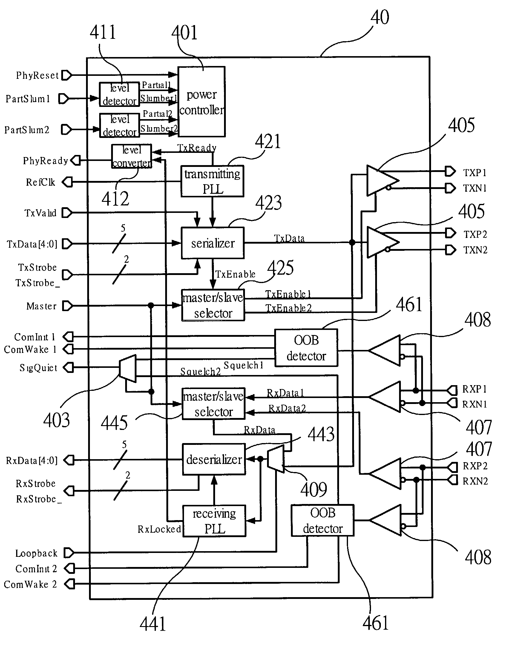
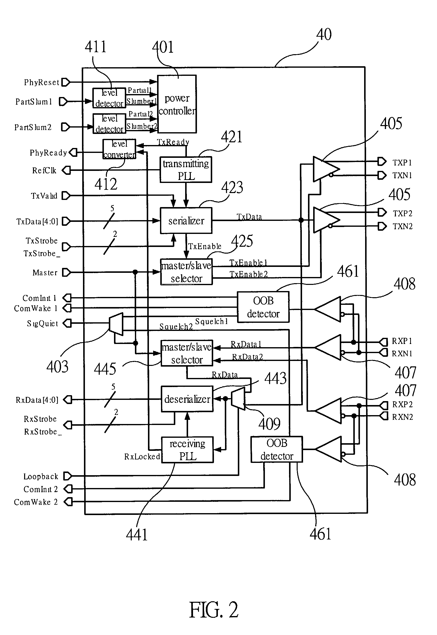
[0026]To start with, please refer to FIG. 2, which is a circuit diagram of a serial ATA external PHY chip in accordance with one preferred embodiment of the present invention. As shown in the figure, the circuit comprises: a serializer / deserializer (SerDes); a phase locked loop (PLL); at least one transmitter 405; at least one receiver 407; and at least one OOB signal detector 461.

[0027]The elements of a serial ATA PHY according to the present invention are divided into two groups, in which a external PHY chip 40 contains a high-frequency analog circuit portion and a storage medium controller contains a digital circuit portion including a 8B10B encoder for converting a 8-bit serial ATA data signals and control signals into 10-bit signals, a 10B8B decoder for converting the 10-b...


PUM

PropertyMeasurementUnit
power stateaaaaaaaaaa
voltage levelaaaaaaaaaa
voltage levelsaaaaaaaaaa

Abstract

A Circuit for reducing the number of serial ATA external PHY signals includes: a serializer/deserializer, connected to a storage medium controller through a set of parallel signal transmitting lines and a set of parallel signal receiving lines, so as to convert signals between parallel and serial specifications; a phase locked loop, connected to the serializer/deserializer so as to generate a clock signal required for data signal transmission; at least one pair of transmitter and receiver, each connected to the serializer/deserializer, each transmitter able to transmit the serial data signal from the serializer through a set of serial signal transmitting lines to a serial ATA device, and each receiver able to receive the serial data from the serial ATA device through a set of serial signal receiving lines to the deserializer; and at least one OOB signal detector, each connected to the corresponding receiving lines, so as to detect the out of band signals from the serial ATA device. The Circuit also employs in certain applications a signal encoding approach for reducing the number of serial ATA external PHY signals, wherein an encoder and a decoder are employed to encode control signals and status signals into special data codes transmitted between a serial ATA external PHY and a storage medium controller, so as to minimize the number of interface signals.

Description

REFERENCE TO RELATED APPLICATIONS[0001]This patent application is based upon Provisional Patent Application Ser. No. 60 / 329,711, filed at the U.S. Patent and Trademark Office on 18 Oct. 2001.BACKGROUND OF THE INVENTION[0002]1. Field of the Invention[0003]The present invention generally relates to an ATA (advanced technology attachment) interfaced Circuit and a signal encoding method and, more particularly, to a Circuit and a corresponding method for reducing the number of serial ATA external PHY (physical layer) signals. The Circuit employs a configuration in which digital means and analog means are separated so as to install the high-frequency analog circuit portion into an external PHY chip. The behavior of the PHY signals and the characteristic of 10-bit data encoding are also utilized to encode the control signals as well as the status signals into the multi-level interface signals or into a special 10-bit data encoding on the data bus so as to significantly reduce the number of...

Claims


Application Information

Patent Timeline
Patent Type & Authority Patents(United States)
IPC IPC(8): H04L1/00G11B5/00G12B5/00G06F13/38
CPCG06F13/385
Inventor CHIANG, CHIN-YIWANG, TSE-HSIEN
Owner VIA TECH INC
Why Eureka
Try Eureka