Graphic application development system for a medical imaging system

a technology of medical imaging and application development system, which is applied in the field of medical imaging systems, can solve the problems of varying complexity and power of these hardware elements, and achieve the effects of easy construction and compilation of imaging applications or specific segments of imaging applications, and easy linking and developmen

Inactive Publication Date: 2006-03-28
GENERAL ELECTRIC CO
View PDF15 Cites 24 Cited by
  • Summary
  • Abstract
  • Description
  • Claims
  • Application Information

AI Technical Summary

Benefits of technology

[0008]Application programs may be created without writing and compiling program code. All program code is contained in the components stored in the library and the selection of components and placement in the workspace area of the display links the program code and any modified properties, or instance variables into a single application program which can be “persisted”. The application program is stored on the medical imaging system along side the component library, and when the application is selected to perform a scan, the program code from the proper components in the component library are linked together per the design of the stored application, and their instance variables set as indicated by the application program. The program code is preferably written in a transportable object oriented programming language, such that data processing components can be easily developed on a first computer system or cpu and downloaded to a second system. Therefore, developed applications can be easily shared among medical practitioners and among medical facilities. Applications can also be developed at an external, off-line computer, thereby allowing for the development of applications without the need to tie up expensive scanning equipment.
[0009]Preferably, the application development system comprises a series of predefined, executable code segments with defined input and output links. The executable code segments can be dragged and dropped onto a graphic building area, and linked together graphically through the connection points to provide application code, which is serialized and downloaded to application specific processors for execution. The graphic building area comprises a plurality of icons which can be easily linked together with a mouse or other input device, thereby making construction and compilation of an imaging application or a specific segment of an imaging application very easy.
[0010]In addition to providing a simple and easy way to program applications, the graphical building area is particularly suited to the development and manipulation of image reconstruction pipelines. Data processing steps for image reconstruction can be graphically modified in real time to modify or improve both collected and visualized data. During real-time processing of an image, the user can modify various parameters, including filtering and threshold parameters, dynamic range and sampling parameters, image resolution, and data flow control in and out of a reconstruction processing pipeline. After a modification has been made, an indication of a change of process and the programming code for processing the acquired data is serialized and downloaded to a data processing board. The data processing board and / or an associated processor preferably translates the programming code to a low level language such as C or assembly which can operate at an appropriate speed to process real-time data. During real-time data acquisition and processing, therefore, a number of data processing parameters and reconstruction parameters can be modified and forwarded to the processing board to modify or improve data imaging and reconstruction.

Problems solved by technology

The particular imaging modality used, and the complexity and power of these hardware elements varies substantially from one system to the next.

Method used


Image

  • Graphic application development system for a medical imaging system
  • Graphic application development system for a medical imaging system
  • Graphic application development system for a medical imaging system

Examples


Embodiment Construction

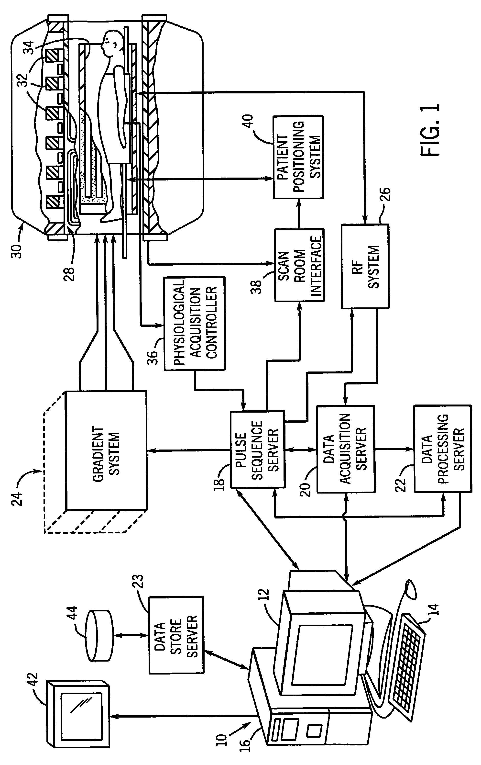
[0025]Referring particularly to FIG. 1, the preferred embodiment of the invention is employed to operate an MRI system. The MRI system includes a workstation 10 having a display 12 and a keyboard 14. The workstation 10 includes a processor 16 which is a programmable machine commercially available from Silicon Graphics, Inc. It is based on a 64-bit microprocessor manufactured by Intel and it runs the Linux operating system. The workstation 10 provides the operator interface which enables scan prescriptions to be entered into the MRI system. As will be described in more detail below, the workstation 10 will run one or more Java™ virtual machines which will run code which is programmed in the Java™ language that is fully transportable to any other programmable machine which is Java™ compatible.

[0026]The workstation 10 is coupled to four servers: a pulse sequence server 18; a data acquisition server 20; a data processing server 22, and a data store server 23. In the preferred embodiment...


PUM


Abstract

A workstation is programmed to operate as an application development system for a medical imaging system. Objects programmed in an object-oriented language are selected from a component library using a visual component assembler which enables them to be dragged from a framework area on a display to a workspace area. Properties of selected components may be edited, and the resulting collection of components may be graphically linked together and saved as an application program.

Description

[0001]This is a continuation in part of application Ser. No. 09 / 721,233, filed Nov. 22, 2000, now abandoned.BACKGROUND OF THE INVENTION[0002]The field of the invention is medical imaging systems, and particularly, systems for developing software applications for such imaging systems.[0003]There are many types of medical imaging systems. The primary distinction between the different systems is the medical imaging modality that is used, such as, x-ray, magnetic resonance, ultrasound or nuclear. In addition, a broad range of capabilities and features are typically offered in each imaging modality. For example, a magnetic resonance imaging (“MRI”)system may be offered with a range of polarizing magnetic strengths and configurations and with a range of different optional features such as magnetic resonance angiography (“MRA”), cardiac imaging and functional magnetic resonance imaging (“fMRI”).[0004]Despite the many differences, medical imaging systems have a number of basic functions in ...

Claims


Application Information

Patent Timeline
Patent Type & Authority Patents(United States)
IPC IPC(8): G06F9/44
CPCG06F8/34G16H30/20G16H40/63G16H50/50G06F8/00G06Q50/22
Inventor DEBBINS, JOSEF P.GOULD, KRISTINE L.LICATO, PAUL E.POLZIN, JASON A.THOMAS, DEEPARADICK, MARK T.SAT, GIORA
Owner GENERAL ELECTRIC CO
Why Eureka
Try Eureka